What's New....
See picture of the truck in action
This page is devoted to providing information on my 1970 C/10 Chevrolet pickup truck. I purchased it in late November 2005. In addition to information specific to my truck, you will find equipment, power team, and VIN number information relevant to all models here, and how to adjust the steering gear.
The 1967 to 1972 style series is very popular, and looking at the lines and proportions of this vehicle, it is not hard to understand why. These models have the smooth, modern look that the 1966 and earlier models don't, without the box-like look of the 1973-1987 series. It is interesting to note that this series is also the end of an era in truck design and construction. These were the last models to offer a true, rugged, and simple truck interior which is actually much simpler than the interiors of the 1960-1966 models and the 1973 and later models.
The 1967 thru 1970 models, which share the same front grill motif, are perhaps the best looking models in the series, and perhaps the best expression of what a pickup should look like. The distinct horizontally-divided grill motif has influenced many of the newer and current models, which also use this motif.
My truck currently resembles more of a '67 or '68 than a '70. This reasons are two: in June 2006, I had an accident which rolled truck, which required replacing the cab. I found a cheap '67 with a small back window. The other reason was the beat up grill. Lame excuse I know. But the 69-70 grills are aluminum and hard to find in good shape, repro grill are outrageously expensive. The 67-68 grills, on the other hand are all steel, and finding one that is straight is not hard. Plus, it looks better with the 67 cab. But the bed, frame, engine, and drive train are still 1970, and the truck is still registered as a 1970. But since the truck looks like a '68, that is usually my answer to people I casually encounter who ask the year.
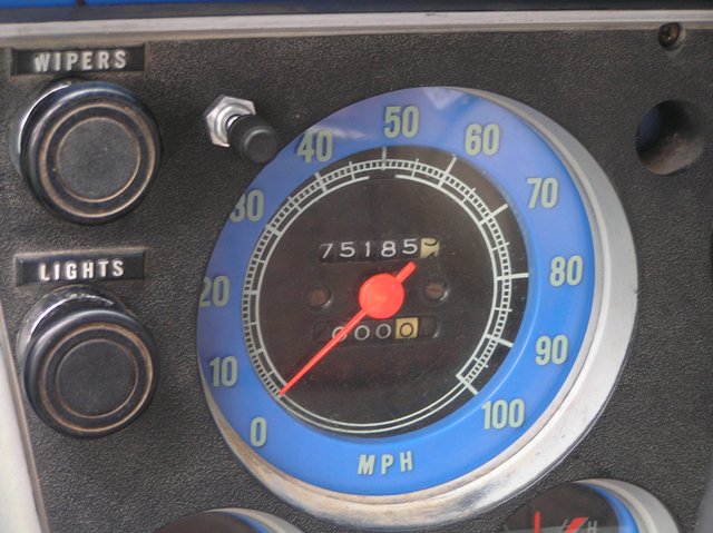
6-27-12: Time for yet another update! Just under 27,000 miles have been accumulated on the rebuilt 305-inch engine without so much as a hiccup! And even with such an excellent record, I have still found things to do. Since the last update I have made two very important modifications to the truck: a trip odometer, and a points-appearing distributor with HEI. Let me explain.....
Above is an illustration of my homemade trip odometer conversion that looks factory. Yes, if you didn't know better, you'd think it should be listed as an RPO on the glovebox door. If you want to add your own trip odometer to your 67-72 truck then read my how-to at 67-72chevytrucks.com. This odometer has been very handy for calculating gas mileage, or seeing how far I've gone on a weekend trip.
The other change, illustrated below, was less for function and more for looks. The standard coil-on-cap HEI looks out of place in a 67-72 engine bay. It is also difficult to get at the cap retainers because of the way it sits near the firewall. And the engine looks like it has something missing without the remote-mounted coil. The solution? A small-body HEI, custom made by Dave Ray.
Below is a picture of the installed distributor and ignition coil. Even tough it looks like it should have points under the cap, there are no points. The distributor uses an MSD pick-up coil and a stock GM HEI electronic module. When used without the ballast resistor, the whole set-up performs like a standard HEI distributor would, but still looks like the stock 67-72 points unit.

10-1-11: NEW TIRES!!!!!

The picture above says it all. I had the factory steel rims sandblasted and powder-coated. The tires are 225 75R15 tires, and they look almost stock size. The tires are Hankook's, and have given very good highway and wet weather performance. They are much better than the Cooper tires I had on it before (you can see them with the aftermarket rims in other photos of the truck).
8-14-11: With just over 9,000 miles on the clock, the 305 is still strong and not burning any oil between oil changes. Anyway, with the truck back on the road, how about adding a cool vintage accessory? I got this late 50's Unity brand spotlight off a board member at 67-72chevytrucks.com. It was missing the switch cover, so I purchased a new one from Unity (current model parts fit old spotlights all the way back to the 1950's), and after buying a 12v bulb for it and the correct mounting bracket, I installed it. It is a neat piece and I thing gives the truck sort of a 'shop truck' look.
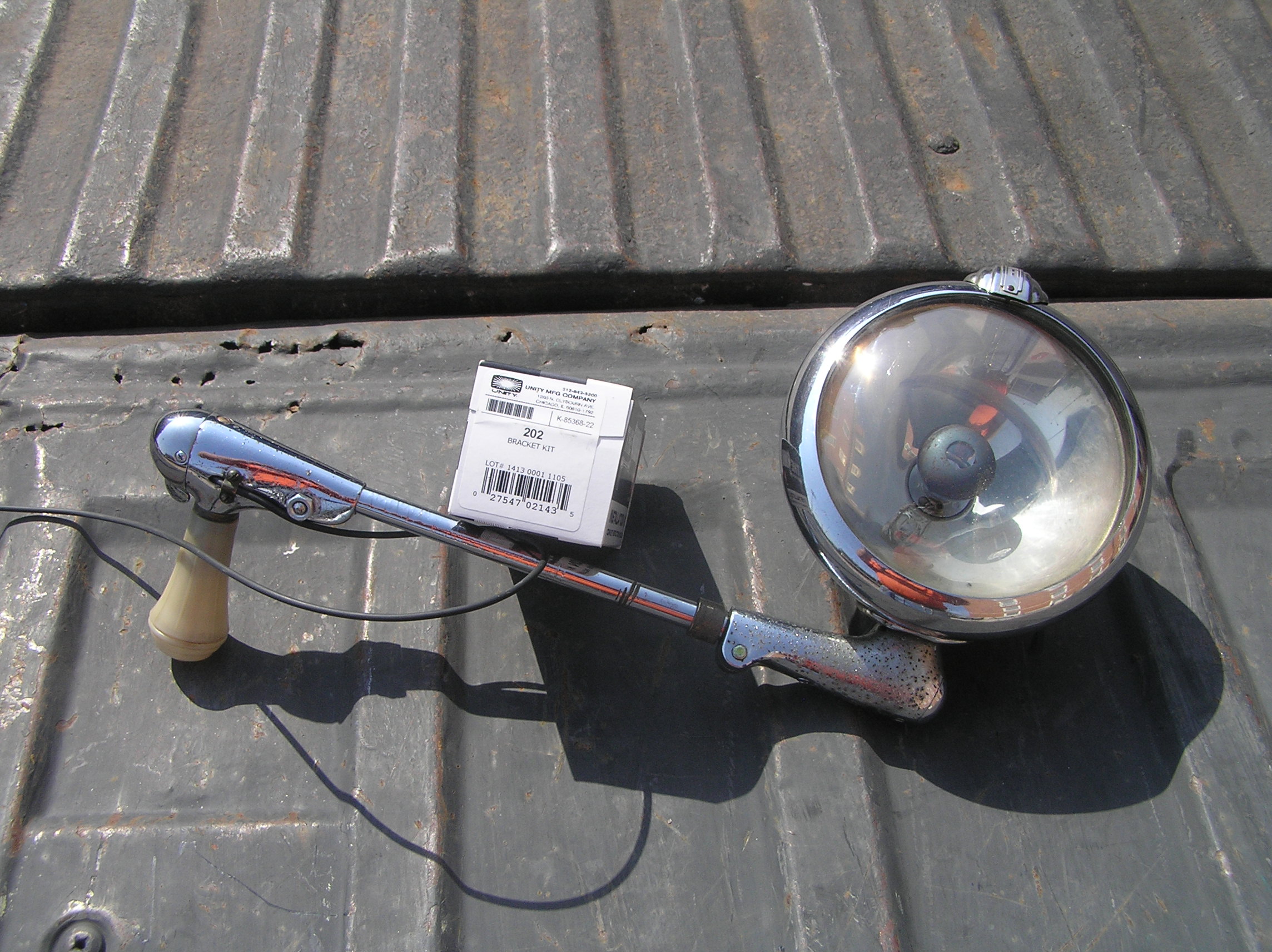
Above, a picture of the spotlight pre-install. This one is old enough, it does not use a sealed beam lamp. In case your wondering, the bracket is #202.
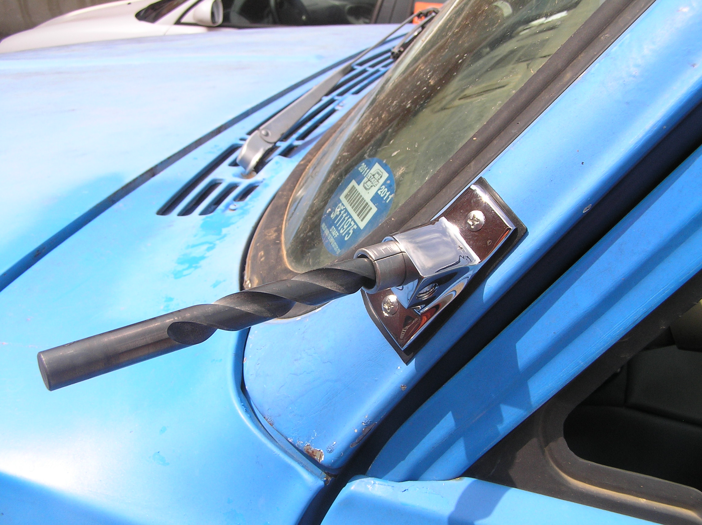
Above, during the install process. This requires drilling a hole in the A-pillar.
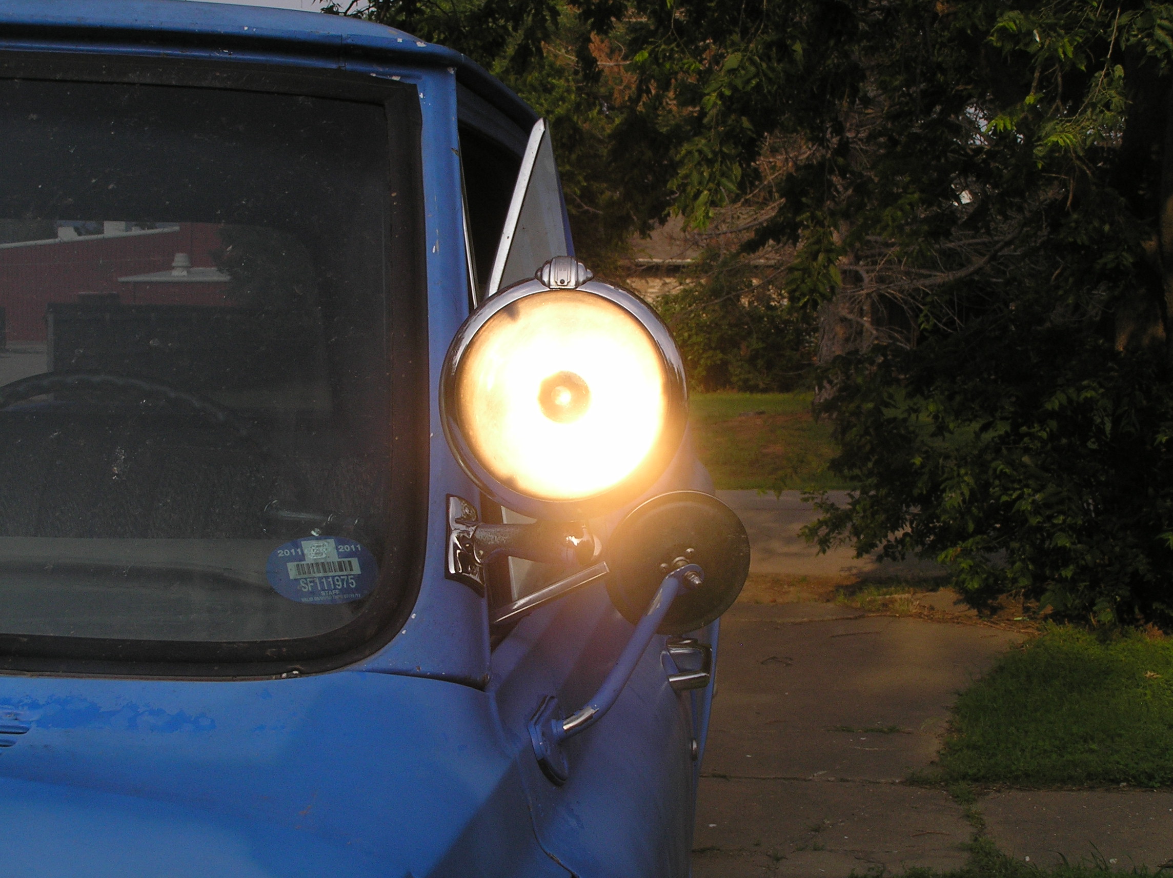
Above, the completed result. I have found having the spotlight very useful at night. I have also, since the original installation, converted the spotlight to use newer sealed beam lamps. It was extremely easy. A 9/16" nut holds the S-5 lamp head on, and by removing this, I was able to install an S-6 head from the 1960's that uses the sealed beam. The light still looks the same with the crest.
3-14-11: Big Update.....Very Big! Not long after the Q-Jet work done in the last update, the 350 decided to throw a connecting rod. The same rod that had had the spun bearing broke 6,512 miles after the rebuild. So, the truck sat while I played with my 1970 Suburban. In August 2010, the thrown 350 was pulled so that another 350 could get the truck back on the road. This engine had been given to my Dad by a co-worker. This engine had some problems and began knocking almost immediately. I did manage to limp about 40 miles of use out of the engine using the truck to carry some plumbing supplies for a project, but after that I parked it.
In December, I decided to rebuild that 305. I started by dropping the heads off at the machinist's. I knew the block was probably good, but wasn't sure of the heads, and I believe valve issues were a big part of the problem with how the old 305 ran. So, I started with them. When they checked out good, I had them done, and after I picked them up, I took the block, crank and rods to be done. The block was bored .030" over, the crank ground .010" under, and the rods checked, and new pistons put on. All parts I purchased online from Summit Racing Equipment, though the engine is very stock. I made some changes though. I used a stock grind camshaft typical for late 60's /early 70's 283-350 engines instead of the late 70's smogger cam. I used flat top pistons, and bumped the compression ratio to 9.3:1. And, I used a Q-jet carb with a stock 68 cast-iron manifold. I did a few nice upgrades, such as a Comp Cams double roller timing set, brand new HEI distributor, Milodon 5 quart stock-style oil pan, and a Melling high volume oil pump.
The engine was assembled on nice weekends between the snow storms of late January and early February, and I installed the engine the last weekend of February. On Feb. 28, 2011, I started it for the first time since July 4, 2009. It has been run, and the truck driven everyday so far since, and has just over 1200 miles on it.
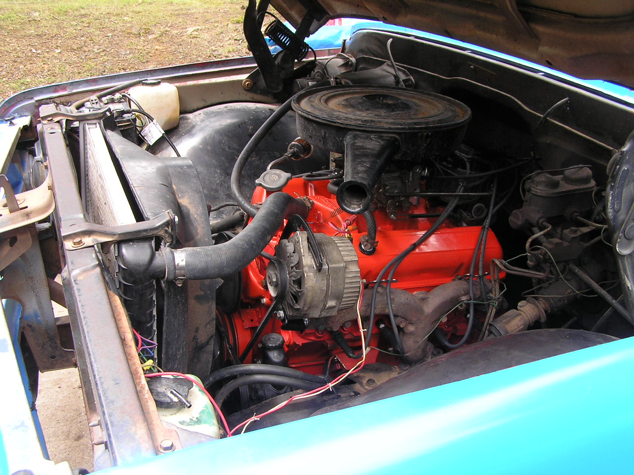
Here is a picture of the 305 back in the truck. Look at this picture, then scroll down to 12/07. Its hard to believe it is the same engine!

Note that I've taken a lot of time with wire routing, and it is really interesting to see such a clean engine bay without the spaghetti mess of wiring usually seen under the hood.
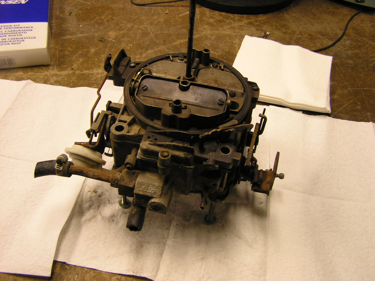
1-12-10: How about an update? Let's go back in time, shall we? Sometime in the middle of December I rebuilt a Quadrajet carb I bought off of a board member on the 67-72 Chevy truck forum. The carb was pulled from a 72 that had sat for a while in some unknown state. It was dirty on the outside, but had all the correct linkages and accessories to work with my divorced choke 68 intake manifold. Here is a picture of it before rebuilding:
Pretty nasty looking, right? Parts of it were still clean, and I found this tag:
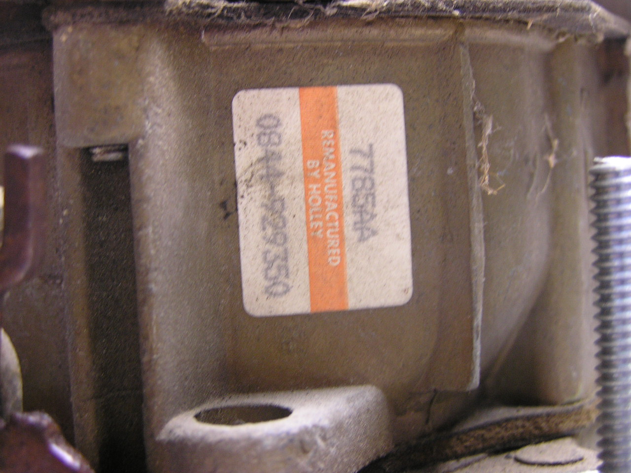
Apparently, it had been remanufactured by Holly!!! Taking it apart....
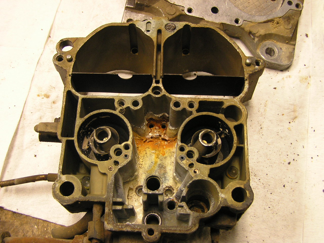
...I found this. Oh!, the perils of buying an old carb. Apparently, water had gotten into the bowl. Since I was rebuilding the carburetor at work after hours, I had access to a sandblaster. The blasting medium we have is some kind of non-toxic stuff that barely removes flakey paint, so after soaking the interior of the carb with carb cleaner, I sandblasted the bowl interior. It cleaned up very well, the medium being so poor that it did not harm the soft metal of the carburetor body. After it was all clean, I discovered that one of the secondary jets was rust damaged. The secondary jets are steel rings pressed into the bowl floor, and a little bit of one of the jets was missing, making the hole oval instead of round. Acknowledging this would have some kind of an effect, I pressed on, and eventually assembled the carburetor:
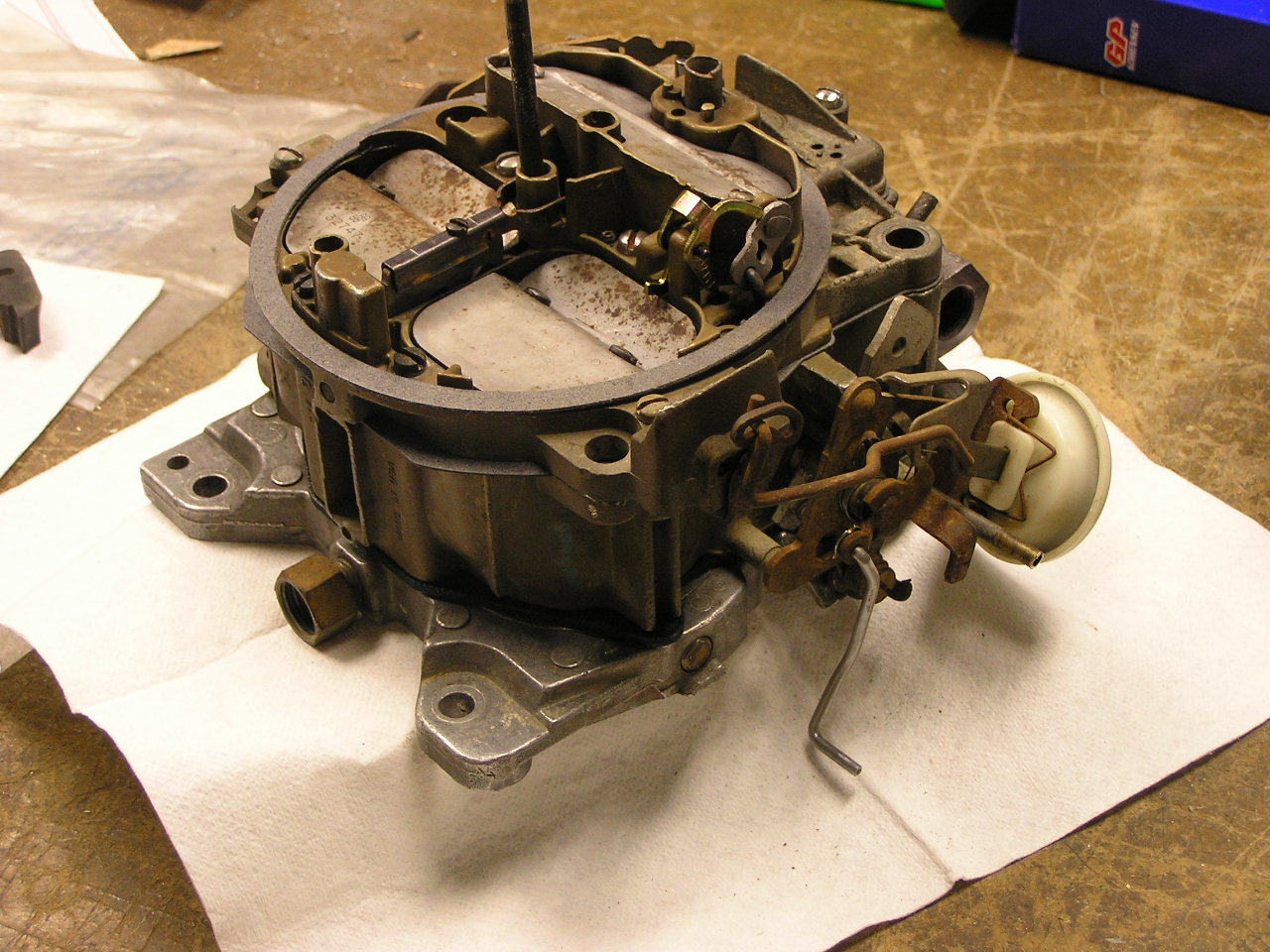
Afterwards, installation of the carb on the truck went successful, and the truck ran quite well. I had to rig a new choke linkage to the coil on the manifold from some 12 gauge solid wire. Once I got it all adjusted just right the choke worked well on its own, it idled well, and part throttle cruising was OK, but higher load conditions were something different. It seemed to lack power to climb hills at speed. And full throttle performance was non-existent. It seemed to do more with the stupid lock-out setup and the air valve hanging up, I think, than the damaged jet. At any rate, After a couple weeks another carb would have to do. I had a couple other Q-jets lying around, a 75 and a 77, and I decided to rebuild the 77, the 75 had the divorced choke set-up, and even though it was working on the 72 carb, it was a pain to set up and wasn't adjustable easily. The 77 carb had electric choke. So I rebuilt the 77 carb and swapped them out. That didn't stop the problems. Though I now had good performance under all throttle and load condition, idle was weird and erratic. The throttle shafts bearing were much more worn than I though.
Above, a picture of the 77 Q-jet on the engine. Like I said, the idle was real erratic, and the carb was off a 77 Pontiac, and thus, had the weird Pontiac linkage. So I had the carb base rebuilt by Cliff Ruggles. While Cliff had it, he even removed the Pontiac bell crank and installed the bell crank off the 72 Chevy carb so it will work better on the truck. He also gave some advice on plugging the extra vent in the air horn (outside the air cleaner circle), and suggested I find a later Chevrolet airhorn with the correct vents. For street use, the way I have it now should be OK. Here's some pics of the carb with the rebuilt base:


9-16-09: How about a few photos of the truck from a bridge hunt:


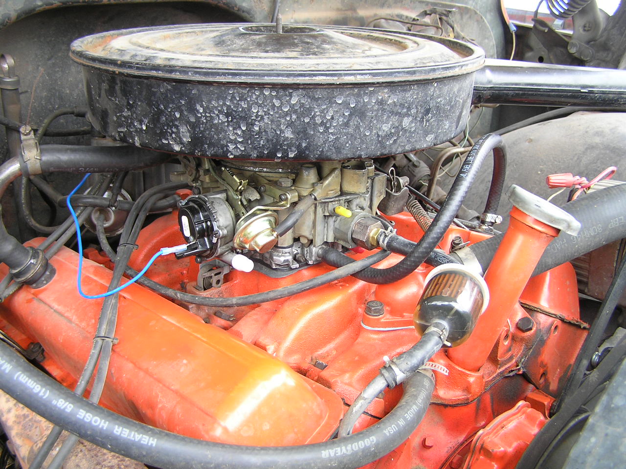
7-4-09: Time for a new engine!!! Actually, its the old 350 that was in the truck when I got it.
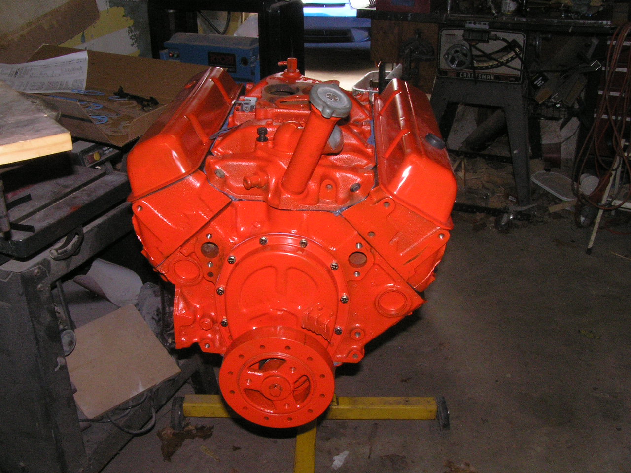
Above is a picture of the engine after assembly. Below is a during shot of me tightening the rod caps to torque.
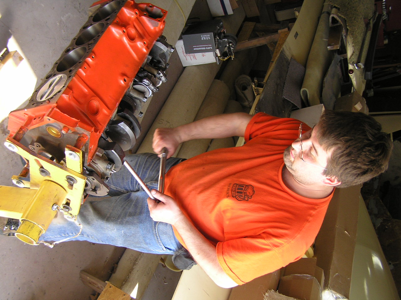
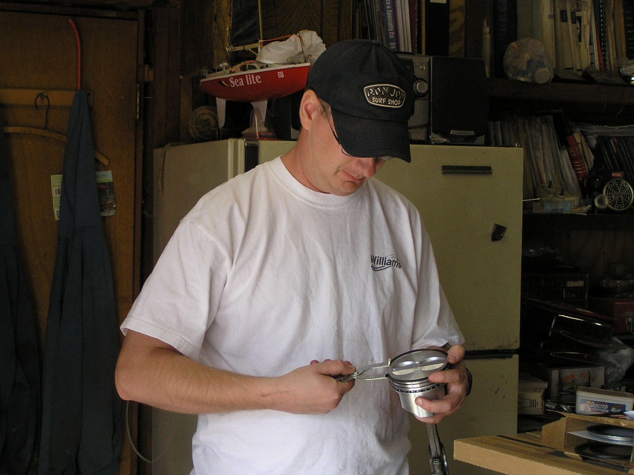
Above, my friends Ken and David, and my father also help with engine assembly. Here is David installing rings.
Below, the new engine in its compartment. You can also see my factory-style coolant recovery system on the right fender. I used a 67-68 style intake manifold to go with the whole 67-68 theme of the rest of the truck. Also notice the truck now has the correct style accessories on the front for the 67-72 series.
April '09 Front clip change: I drove the truck to Colorado in February to buy a nice 1968 Chevy front clip. It was a nice trip and I really enjoyed taking the truck on a road trip. The tired old 305 had some altitude sickness as I headed west that became noticeable when I got into the Oklahoma Panhandle (yes, and you forget too that Oklahoma and Colorado are neighbors. I didn't go thru any other states). Luckily, I carried a carb tuning kit with me and was able to do a little adjusting to keep things managable.
Anyway, here is a picture at the Oklahoma Colorado state line:

I really don't know why the picture came out unfocused, unless the camera just didn't like the cold, which is possible.
And here is the truck wearing its new front clothes:
Below is sort of a step-by-step series of comparisons of the truck's front end changes:
 |
 |
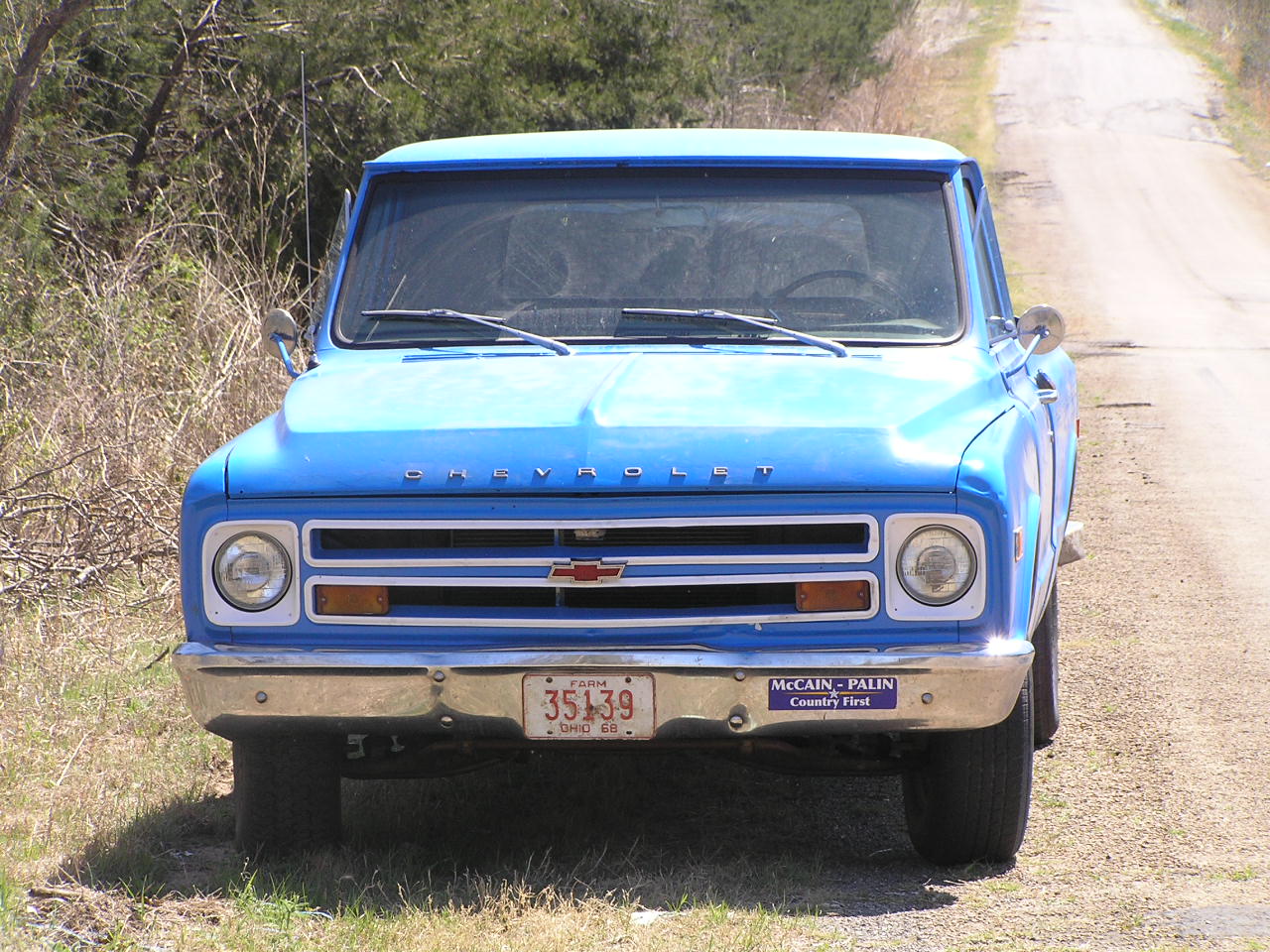 |
Above left to right: the beat up old '70, and yes in April '08 I decided to paint the cab roof blue; '68 grill & hood with '70 fenders, this was kind of a transitional point as I had pulled the grill and hood off a truck at a local salvage yard and decided I was tired of looking at that ragged old '70 grill so I painted them and stuck them on in June 2008. Note that this combo doesn't let you use the trim rings that go around the headlights because the headlights are in just a slightly different place on a 69-72 radiator core support. And finally, the full 1968 grill. As you can clearly see, the 67-68 and 69-70 styling motif are very similar with the two horizontal openings/horizontal grill bar. I think the lines are just a bit cleaner on the 67-68 grill without the optional extra trim as I have done it here. Also the use of painted trim versus chrome trim for the openings and bezels makes tem look cleaner, and stand out more.
12-15-16-07: Cold weather is really taking its toll; time for a cam and intake swap. That's right, out with the old, tired, cruddy crap, and in with bright shinny, new parts:
Before. This engine has never been opened since it left the factory in 1977.
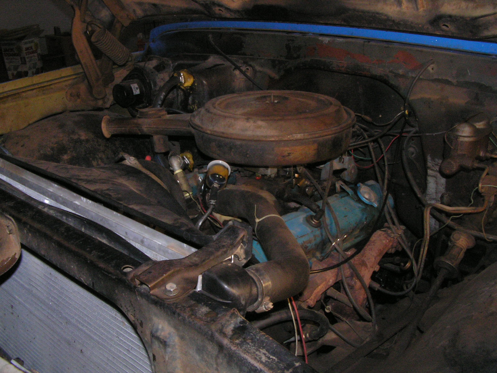
Last picture with the carb and intake still in place. Carb was a 2GC that I rigged about a month ago as a manual choke (see on down).

During, pretty nasty. Everything had its share of varnish and carbon deposits.

Removing factory lifters:
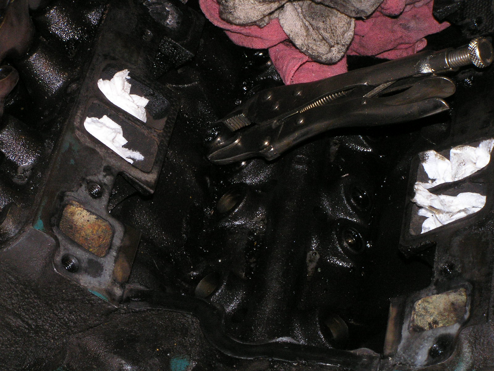
This disgraceful thing is the old intake. Pure 2-barrel emissions choked junk.

The new intake: a Weiand Stealth manifold.

The new carb: An Edelbrock AFB. You'll note the manual choke lever is missing in this picture. I had used it on the old Rochester 2-barrel for the last month or so. It got put back on when everything was done.

Bright and shiny on old and nasty.
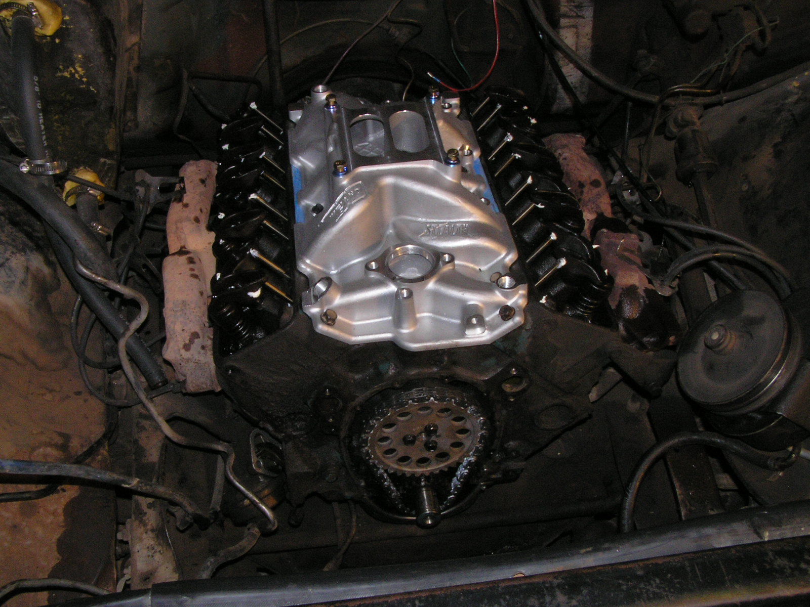
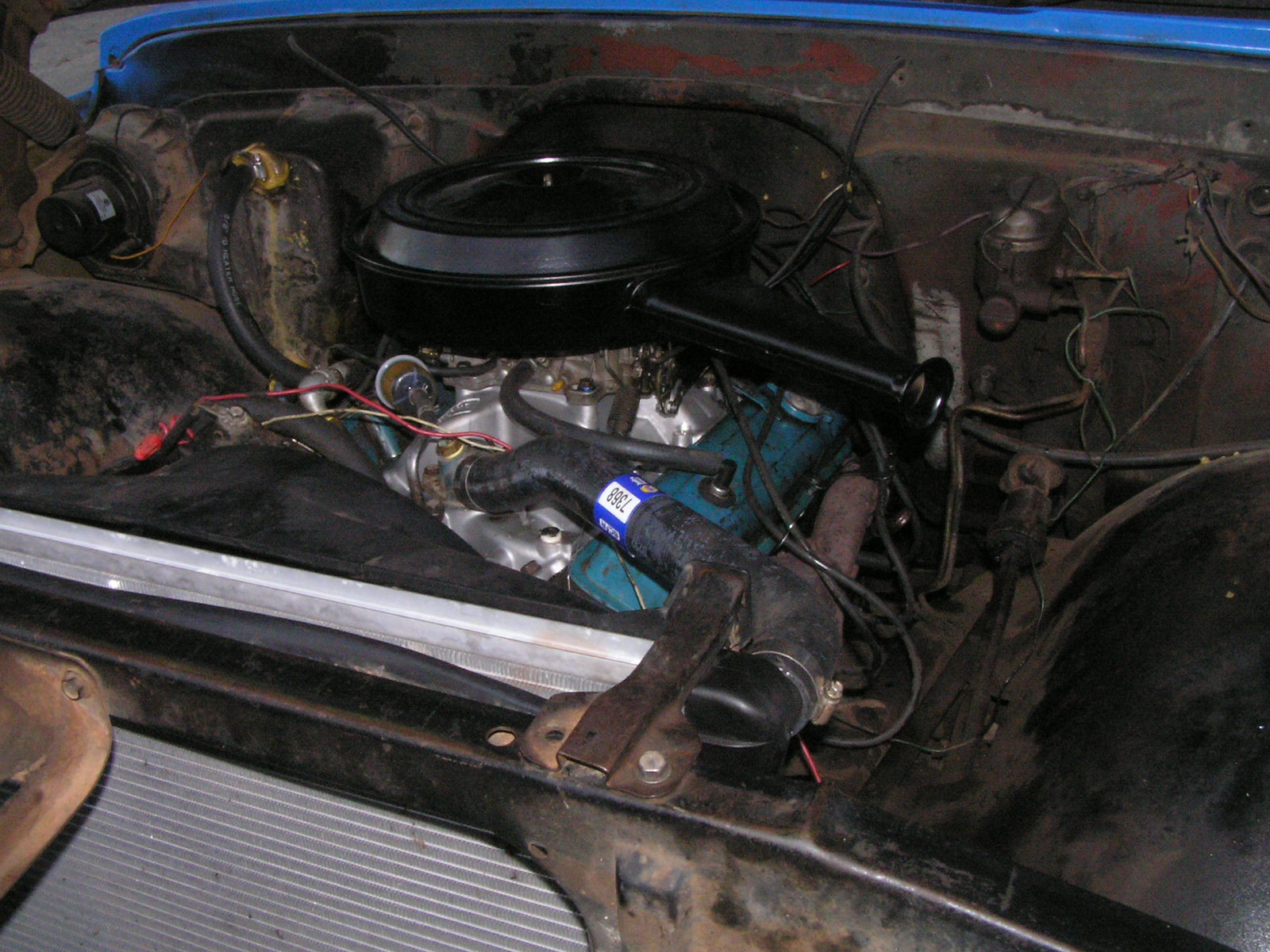
It is done! The air cleaner actually came off of a 1968 c/10 truck with a Q-jet and 327 engine. It was rusty and had insect nests in it, so I cleaned it up and painted it.
11-17-07: New Dash! I decided to cut out the old, hacked-up dash panel and install one I got form the truck forum. It came out of a '69, and after some cleaning and paint, it looks quite presentable. Here are some after shots:
The holes in the dash you see below are for a little plastic legend that says "ACC-OFF-RUN-START".
A few days after taking these pictures, I converted to factory-style manual choke. The wiper washer knob you see above became the choke knob.
8-11-07: Power Steering Time!!!! I bit the bullet and decided to upgrade to power steering. The power steering gear box is a remanufactured unit, not a used one. I got it at O'reiley's Auto Parts. I did go and buy a $10 salvage yard box for the core.

Last look at the old gear box. Scroll down to 4-5-06 to see when this one was installed.
Sorry, no in-betweens, but this is the end result. I replaced all the tie-rod ends and idler and used a new rag joint and pitman arm.
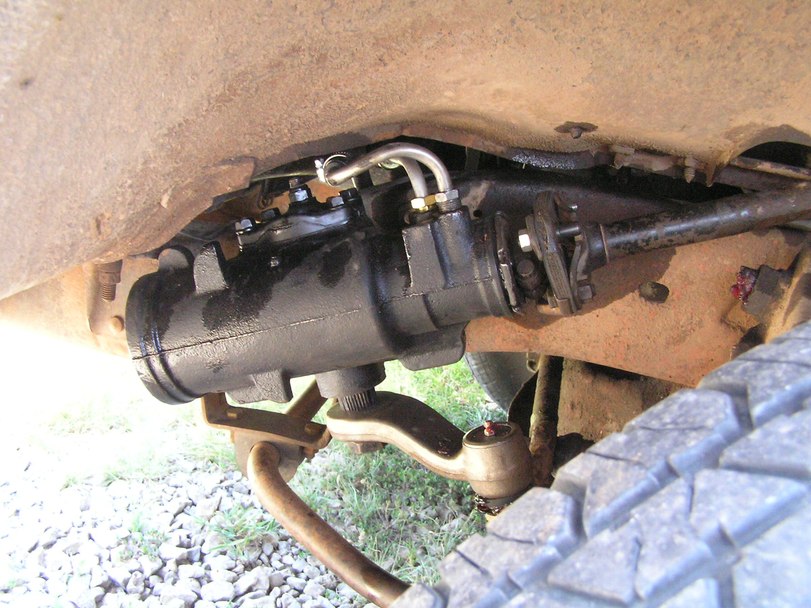
The power steering pump is used. To use this pump, I had to get a new water pump, and get the alternator and exhaust manifold brackets from a 1975 truck without a/c.

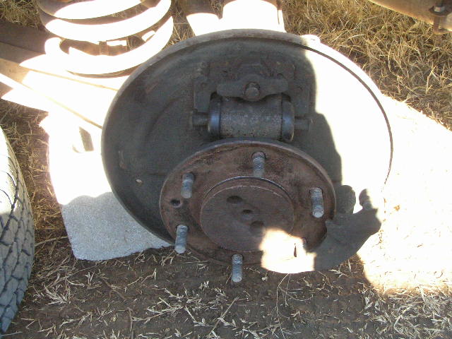
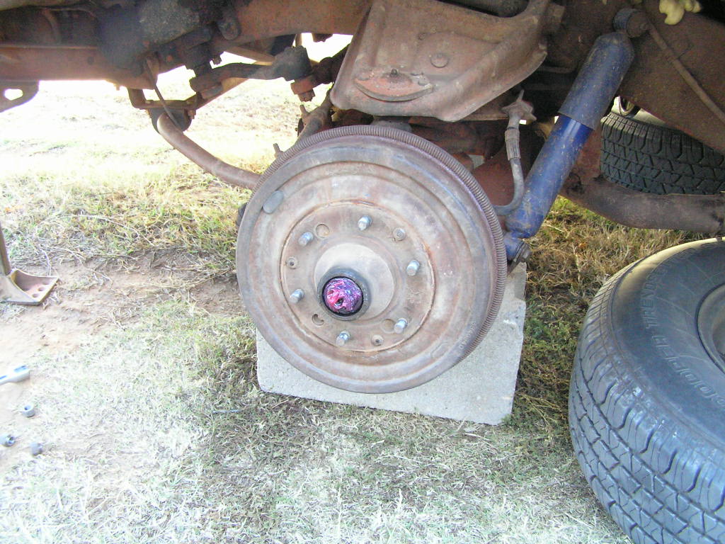
2-19-07: Weather was finally nice, so I got those pesky parking brakes installed. Here's some pictures:


Above two pictures are "before". Previous owner apparently didn't understand how parking brakes worked; cable was broken and frozen on pass. side, and the spreader bar was missing on driver's side, as well as another frozen cable.
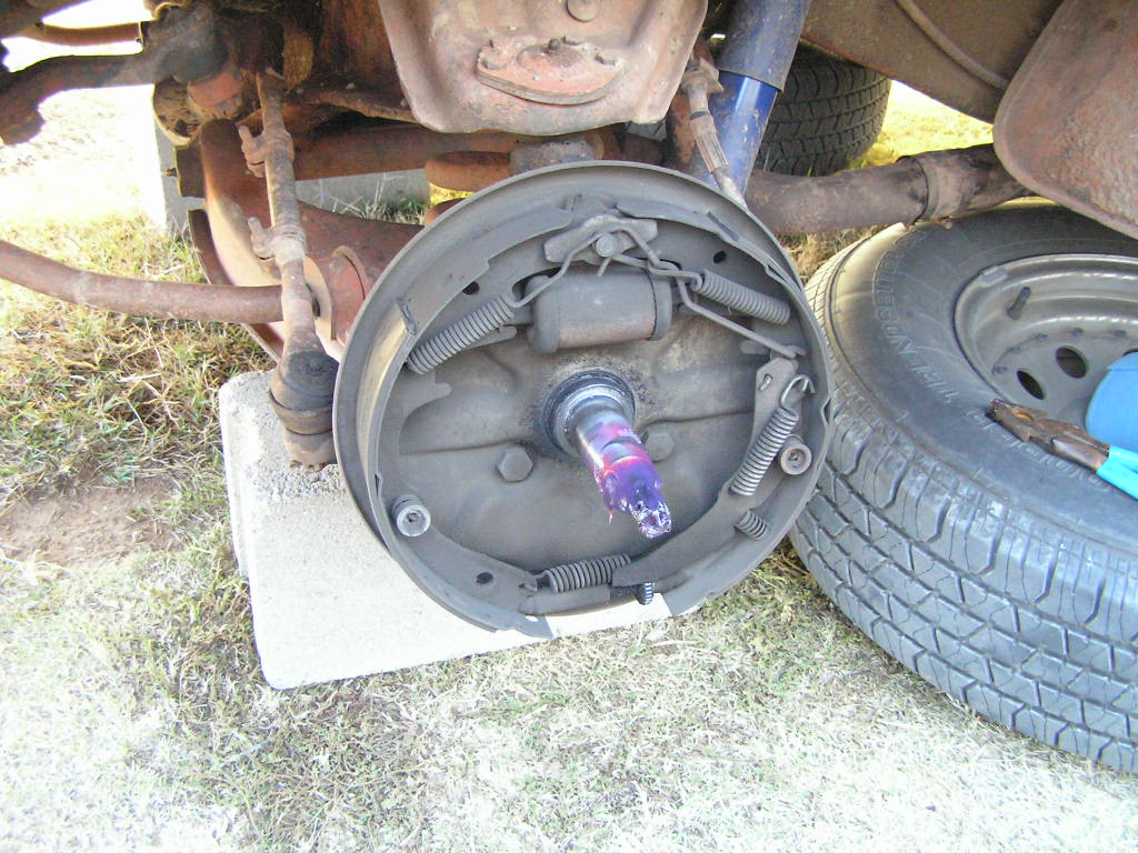
A few "in progress" pictures:
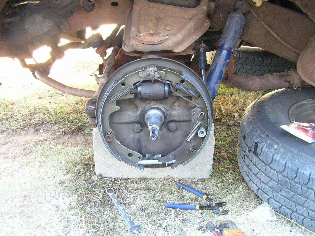
Above, no shoes....

Above, removing the cable clip from the trailing arm....

Above, unclipping the cable....

Above, unhooking the parking brake lever from the inner cable end...
.... then use a screwdriver and (below) break off the little spring fingers that hold the cable to the backing plate.....

....and pull it out (below).

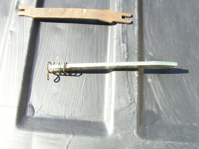
Above, the new brake bar with the spring correctly installed. I got this part, as well as the rear cables at NAPA, however, the parts guy will say it is listed only for 73-87 1/2 tons. The 67-72 1/2 ton drum brake parts are all the same, so don't worry. The original 1970 bar is shown above for comparison.
Next, you've got to replace the front cable. The only difference between the 67-68 and the 69-72 cables is the 69-72 cable is longer. Start by backing off the equalizer nut. If your cables weren't froze up, I'd recommend starting here; however, if they are rusted solid as mine were, it makes no difference. The nuts have 1/2 inch flats, and the other parts has flats for a wrench like you see below:

NOTE: This is where you adjust the parking brake when finished!!!!
Back the check nut off first, it will cut through the grime, and clean it off, then remove the adjuster nut. The old nuts will fit the threads on the new front cable if you choose to reuse them.
The 67-68 style cable has just one clip....
....located in the fender well securing the cable. The 69-72 cable will have an additional clip. Remove this clip and....

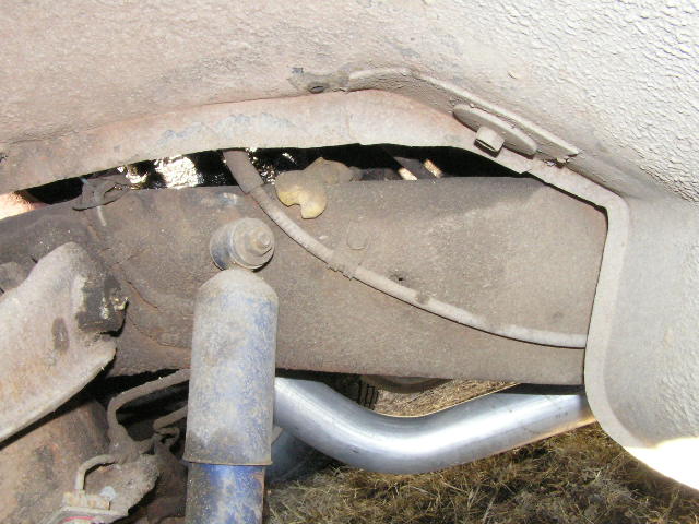
Unclip the cable where it passes through the frame here. The cable is clipped to the frame just like the rear cable were held to the brake backing plates; you'll have to break off the little spring fingers with a screwdriver from the inside side of the frame.

Above, this picture of the new cable attached to the hand lever assembly will clarify removing the upper end of the cable from the cab. The foot lever attachment is similar. Simply cut the old cable near the shackle where it attaches to the lever, loosen the clamp bolt and any other clamps, and pull it through the hole in the firewall into the engine compartment,
The shackle that attaches to the lever is too big to go through the hole in the firewall, so when installing the new cable (below) start by threading this end through the firewall hole....

...into the engine compartment and, routing it along the path of the original cable, down into the hole in the frame until....

.... this spring clip snaps into the hole shown above.
Now for some "after" pictures:


Above, the after views. Note the new springs. The bottom picture compares the 67-68 steering column cover with the later 69-72 type. Since my cab is a 67, I decided to use the 67-68 hand lever, the holes in my firewall are already set up for this. Mounting the hand lever was easy, as was adjusting the brakes.
To adjust the 67-68 parking brake: Note, the service brakes must be properly adjusted before attempting to adjust the parking brake. First, apply the hand brake lever 4 clicks from full off, then adjust the adjusting nut until a moderate drag is felt when spinning the rear wheels. Release and check that the brake is fully relaesed; if not readjust. Tighten the check nut against the adjuster nut,
To adjust the 69-72 parking brake: Same as the 67-68 procedure except apply the foot brake 1 click from full off.
Also note in these pictures you can see my new dual exhaust system, which is much better than the ratty old single set-up I had before.
2-12-07: Waiting for some parts to arrive, so I decided to repaint my gauge needles

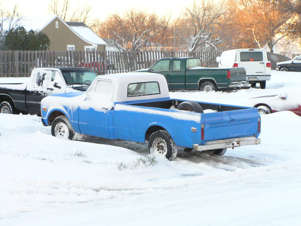
12-15-06: The truck is now blue and white and covered in snow
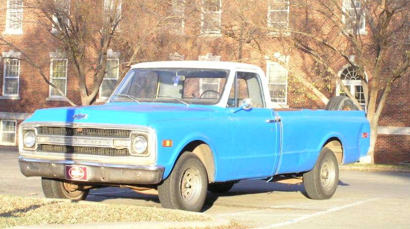
Non-snow picture of the truck after painting:
11-30-06: Time for new brakes!!!!
That's right!! New shoes all the way around, new hoses, rebuilt all four wheel cylinders, and new adjuster nuts in front, and the old front adjuster nuts installed on the rear. I've decided that's how I'm going to handle the adjusters at each brake job. Here are some pictures (sorry, I only took pictures of the front);
Before:
And after:
It is simply amazing how well properly adjusted manual drum brakes stop, After about 2-3 hundred miles the shoes were properly bedded in, and stopping was quite impressive. because of the self-energizing property, I have almost completely forgotten they are not power assist.
9-11-06: It's sway bar time!!!!!
That's right, the single greatest handling improvement that can be made on one of these trucks was realized this weekend with a sway bar!!!
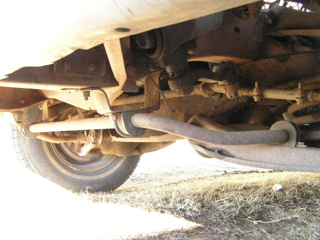
Above, the sway bar. The bar actually came off a 1979 Chevy 1/2 ton. All front sway bars for 1/2 tons are the same from 63-87!!!! And an easy way to upgrade and get better handling on corners and curves is to get a sway bar from a 3/4 or 1-ton truck. The only difference is the diameter of the bar. The heavy duty sway bars for 1/2 tons are the same as the 3/4 and 1 ton bars. Since my truck never had a sway bar, I got all the mounting brackets off the salvage yard truck. Cost was $25. I used new grade 8 3/8" bolts from Lowe's, and new bushings from NAPA.
On the highway, the truck is much more stable and handles curves in the road at speed. Especially at highway speeds before bumps in the road made the truck feel unstable and shaky. The sway bar adds a lot of stability, whether on a straight road or a curve; and banked curves are handled much better too, with less tendency to drift.
8-15-06: The truck is once again a uniform color: primer grey. Inside of bed and tailgate still gold, however.
7-17-06: First pictures of the truck after being roadworthy again. I have created..... A Frankentruck!!!! What is is now: A 1970 truck with a 1967 small back window cab. This unusual combination will take my intended plans into different direction. Here is a picture of the "Monster" with its old head in the bed:

Since the cab and front clip was off for about a month, I was able to do a very easy total front end rebuild
6-4-06: Rather unfortunate accident yesterday has left me truck less, at least for a while, until I get things fixed. here's a picture:
Tire blew, and she swerved, and then rolled over. Landed just as you see.
4-5-06: Here are pictures, with comments, from my steering gear replacement

The first picture here is of the "new" steering gear. Looks nice, and feels pretty tight. I got it from 108 Auto Salvage, and it is used.

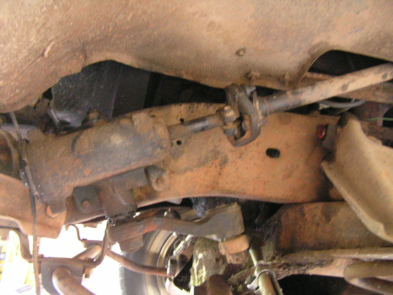
A view of the old steering gear still mounted in place. It is well coated in gunk.
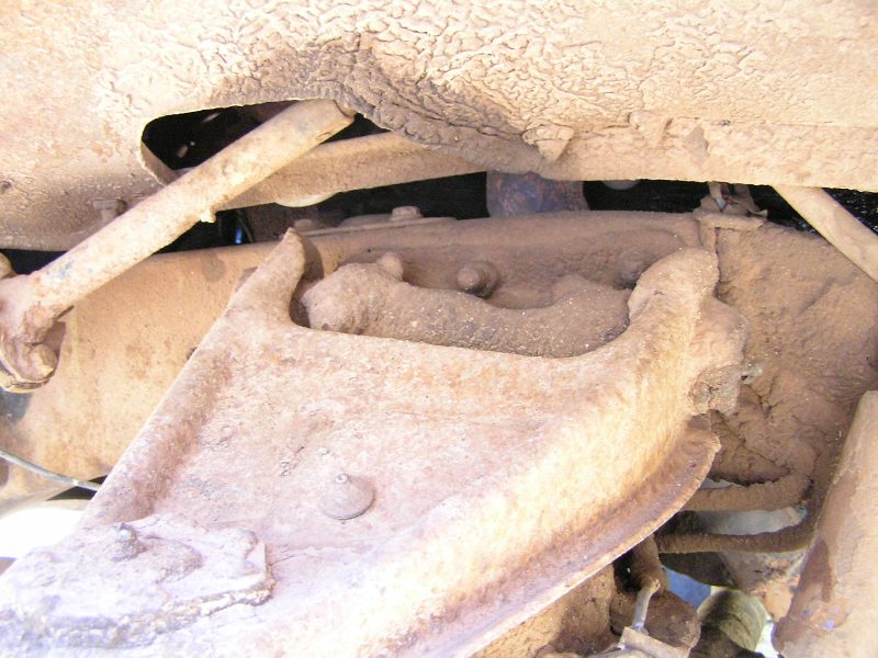
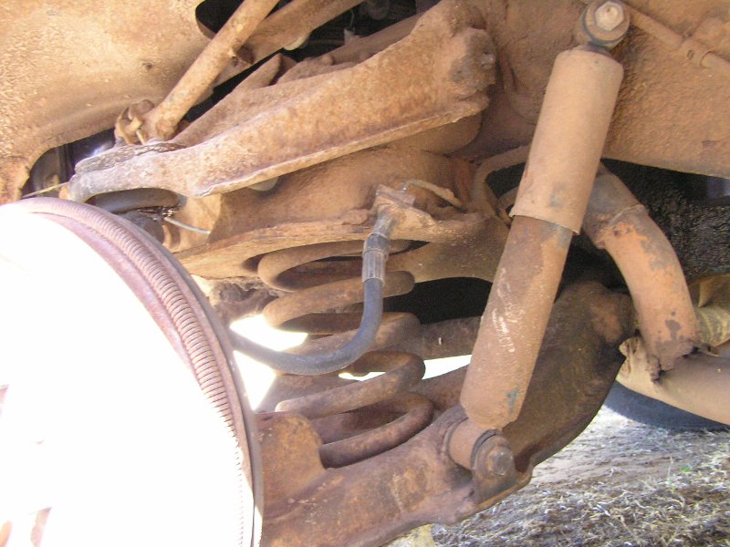
Above are a couple of view of the suspension. This truck uses the conventional long-arm-short-arm double wishbone control arms.

Sorry, no in-between views, this just shows the steering gear after it was installed. Before reconnecting the pitman arm to the relay rod, I followed the shop manual's instructions for adjusting the pitman arm sector gear lash. This has to be done with the steering linkages disconnected form the gear, and with the gear centered. To center, count the turns from lock to lock, and then turn the wheel back half this from the lock. After centering, simply loosen the locknut on top of the gear with a 5/8" wrench, and tighten until all the lash is taken out of the gear. To check for this, hold the worm shaft with one hand to keep it from turning, and with the other hand move the end of the pitman arm. Adjust until you can't feel any play when you try to move the arm. Then, you must check that it hasn't been over tightened by turning the steering wheel. The steering wheel should turn free and easily throughout its travel. (the manual will tell you to use a torque wrench to measure the effort required to turn the wheel, but you should be able to do it by "feel" without). If you feel a slight resistance or tight spot, then back off the lash adjuster slightly and recheck. Remember, you have to have the gear centered before adjusting or checking the lash.
The steering is now very tight, with much less play (of course, anything less than what it had is an improvement). With the old gear, you had over 1/4 turn of free movement of the steering wheel before it would turn the wheels, now it is maybe 1/16 of a turn or so. This gear would probably be a lot tighter if I was to replace the pitman shaft bushing, but the play is so slight and the steering is sufficiently tight now.
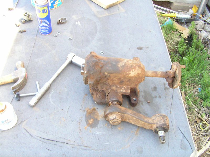
Above, the old steering gear. This gear is so worn, I doubt it could be used as a core in buying a rebuilt gear. The only thing still tight in this gear is the worm shaft end play. There is considerable lash in the pitman arm, and the pitman shaft bushing is very worn. This gear has seen a lot of use.
After the gear was installed and tested, I took the truck out on its mission: Bridge Hunting. Here are some photos:


Above and below, the truck is poised on a bridge that is 100 years old this year (2006).


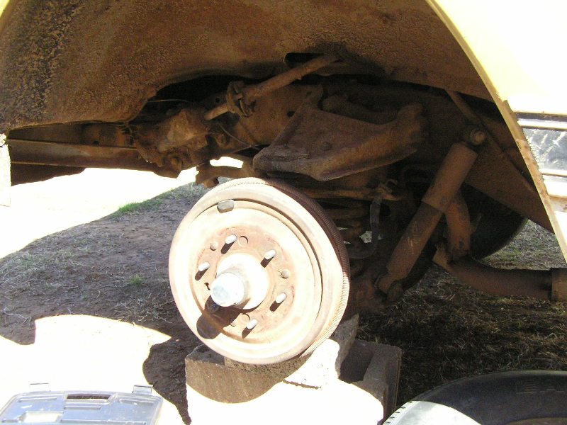
2-20-06: Only had the truck on the road for a few months and a wheel bearing went out. Had to remove the front left spindle to fix it.

I have re-ordered the page and put what was once the top of the page here since so much has changed about the truck since the accident of 6-4-06, so, I leave it here unaltered as a
***Tribute to the Old Gold 1970 C/10***
The CE10934 is, as you will see from the photos, a Fleetside longbed model with a 127-inch wheelbase and V-8 engine. My truck's dimensions are 207 3/4 inches long by 79 inches wide by 70 inches tall. Unloaded curb weight is 3,737 pounds. These were available in many colors, and mine is medium gold and white.
The engine that currently lives under the hood is a 1977 vintage 305 V8 with well over 185,000 miles. The engine that came with the truck was, to put it nicely, very abused and made a knock. (loose rod). There is some debate about whether it was the original engine or not, as it had a few features not available or commonly found as stock on a 1970 truck, such as a later style integral coil HEI distributor, and a Delco SI series internal regulator alternator mounted on the passenger's side. These are easy upgrades, but it seems unlikely someone doing these modifications in the "jurry-rigged" way they were executed would go through the trouble to mount the alternator on the other side of the engine with the new style bracket. Personally, though, I find no objection to this, because the right side mounting lines up better with the pulleys and uses a shorter belt. For appearance purposes, though, I may convert the distributor to the early style HEI with the separately mounted coil, and put the alternator back on the left side with the long slotted bracket. The carburetor on the 350 was a 2-barrel Rochester model 2GV. When the engine is eventually rebuilt, the carburetor will be upgraded to a more reliable integral thermostat Rochester 2GC, or possibly a Rochester Quadrajet, but no aftermarket models, as I don't like the way they perform.
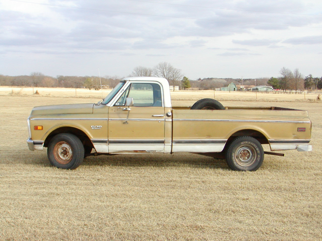
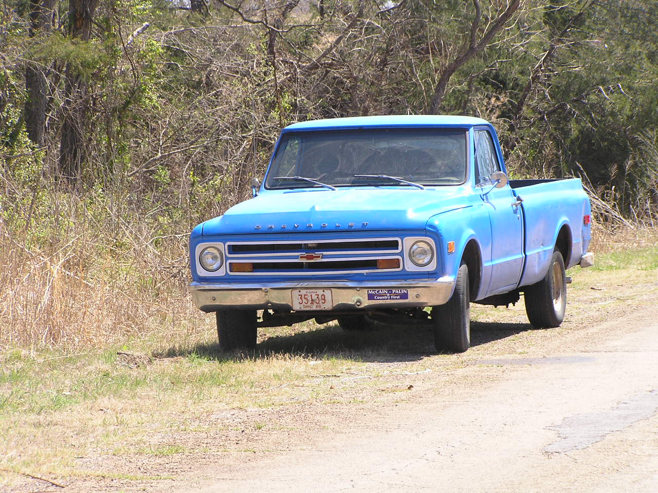
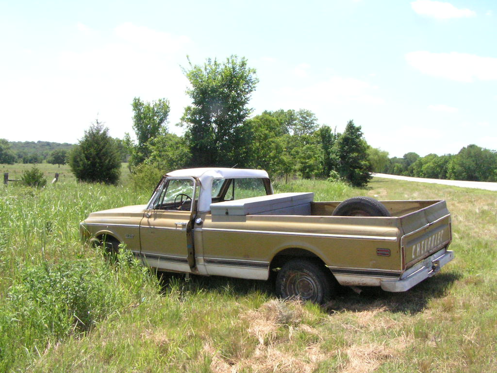
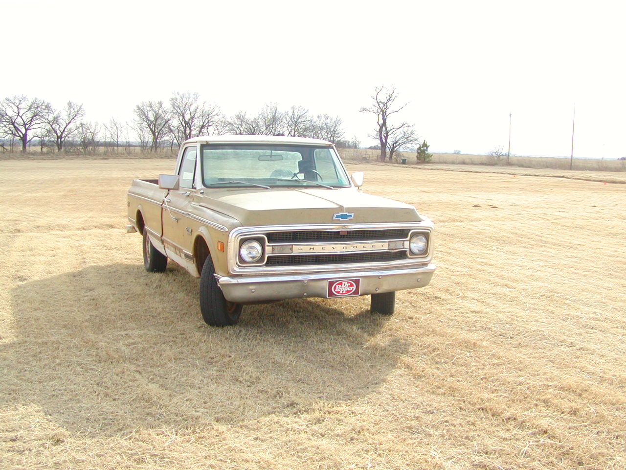
Above, a side view. Yes, I know it isn't in pristine condition. It is all there and with very minor rust, mainly in the rocker panels under the doors and in the right rear cab corner is a dime-sized hole. During this period, these models were available with a two-tone paint scheme that was always the primary body color and white. This is the less common two-tone scheme, as the more common scheme was white paint between the upper and lower side moldings and white cab, and primary color everywhere else.
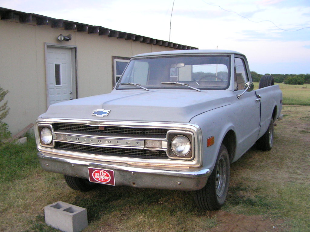
Below, front/side view. The aluminum front grill has a dent in the area of the left parking light. The other problem area, around the hood latch, seems more deliberate, as a futile attempt for the grill to clear the release lever. I have tried to straighten it out a bit and solve the problem, but I am going to need another grill. Also note the unoriginal Ford-esque mirrors. In addition to the stock mirrors, there are holes in the doors for at least one set of tripod style mirrors.

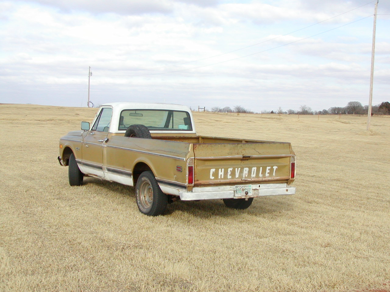
Below, a side/rear view. The painted rear step bumper seems to be the most popular type on this model. Although beat up, all the bed and tailgate trim is present and installed, a rare find.

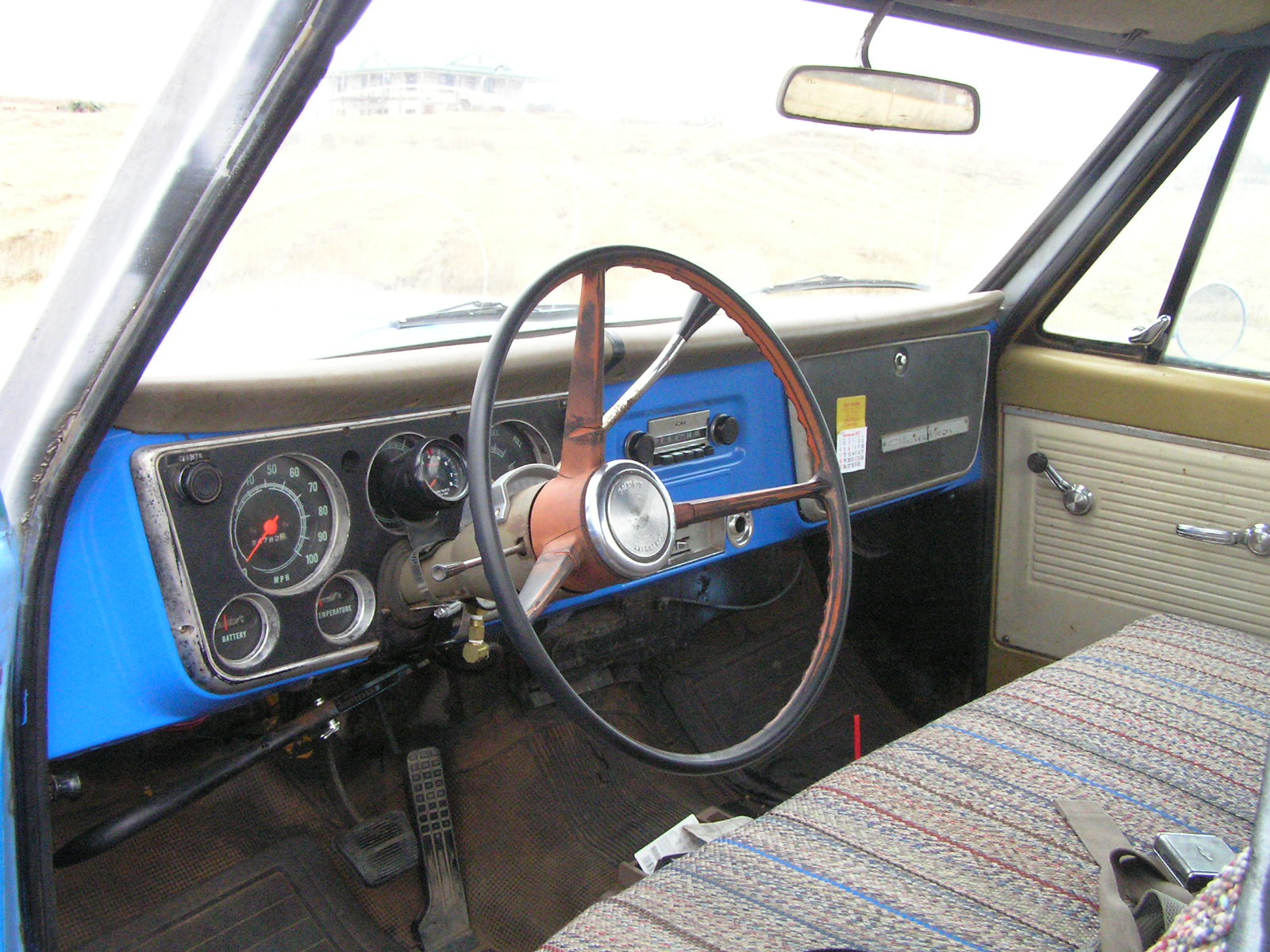
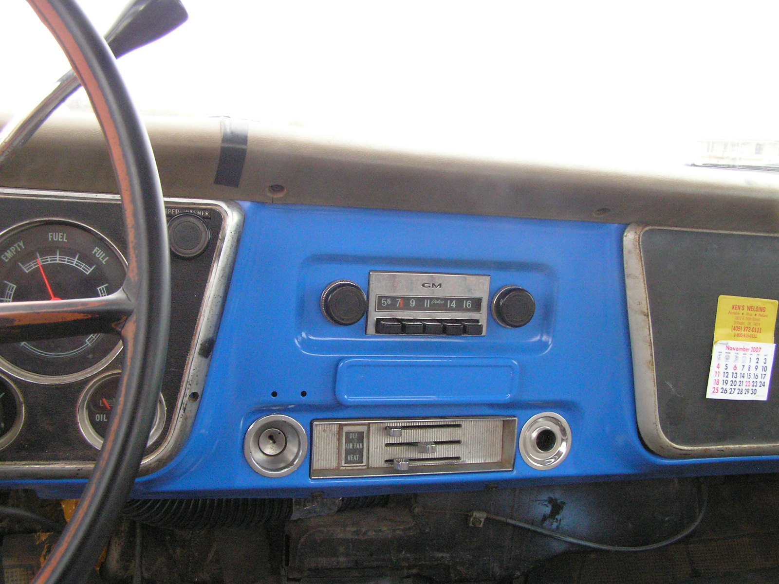
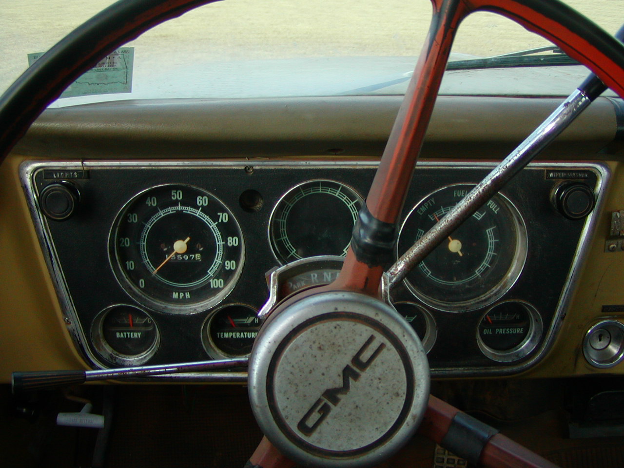
Above, the Spartan interior. Very few parts you see here are not metal. Even the door panels are metal. Note the simple, smooth lines of the dash board, and the symmetrical use of round corner trapezoids for the instrument panel and glove box door. Medium gold, off white, and brown, with black rubber floor covering, are the colors used in the interior. The red 3-spoke steering wheel is not original; it should be brown and have only 2 spokes. It is, however, correct to the '67-'72 series, because it was used on the 1967 and 1968 models. I plan on keeping the wheel, but painting it brown to match the steering column trim.
Below, the instrument panel. All the essential hand-operated controls and gauges are found in this picture; the column mounted shifter for the automatic transmission, turn signal, horn button (which, as you can see is from a 67 or 68 GMC) and steering wheel, turn signal (hi-beam/low beam switch is foot-operated, the way all dimmer switches should be), light switch, and wiper/washer control. You can also see at the bottom left the parking brake release handle, and to the right of the panel, the ignition switch. All the gauges needed for vehicle operation are shown; speedometer and odometer, space for optional tachometer, gas gauge, which includes engine temperature and brake warning lights, and across the bottom of the panel, ammeter, temperature gauge, space for optional clock, and oil pressure gauge. No one should own a vehicle without full gauge instrumentation.
Below, comfort controls, such as the radio and heater control, are placed in the space between the instrument panel and the glove box. Behind the calendar is the cigarette lighter. A past owner had a CB in this truck, and the microphone holder can be seen next to the radio. You may have noticed in other photos speaker in the cab corners at head level. These were connected to the CB system, and not the radio. The CB unit was mounted to the ceiling on brackets which are still there.

Above, a view of the right/front. I have the missing trim piece that goes on the door, but I have not re-mounted it yet. Although this truck is still in the rough and looks like a work truck, I plan to refurbish it, a little at a time. My primary purpose for this truck is for use in the bridge hunts associated with photographing bridges for Oklahoma Bridges. The higher ground clearance will allow us better access to bridges on roads a car wouldn't be suitable for. With that in mind, it will be more important, for the moment, to concentrate efforts on only those parts that effect is driving dependability. Right now, that seems to be the front suspension, which needs rebuilt, and the rear axle ratio, which, at 3.73, is not suitable for highway cruising. I am planning to install a 4-speed automatic transmission, which should give better economy in addition to better highway cruising. I was initially opposed to the idea, in favor of changing the rear axle ratio, but the engine RPMÆs would be better with the 3.73 ratio and an overdrive gear. I will probably use a THM700R4 transmission. This transmission should also work well with the present 305, and with the 350 later when it is rebuilt. The 350 could also be tailored slightly during the rebuild for good low end torque when cruising in the 1800 to 2300 RPM range.
Here are some pictures of my VIN plate with all the optional equipment
installed on my truck.
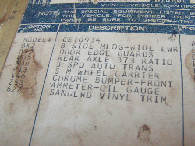
Here are the factory installed options. Please note that some variations may occur from truck to truck in the way the typist abbreviated the options when making this list.
À BX2 B SIDE MLDG-WIDE LWR This referrers to the trim along the bottom of the truck.
À B93 DOOR EDGE GUARDS This referrers to the bright metal edging applied to the back edge of the doors to protect them from scrapes and scuffs.
À H05 REAR AXLE 373 RATIO Since my truck was fitted with both optional 350 cu. In. V8 and an automatic transmission, the ratio would have been 3.07 for these options. The original buyer, however, wanted the 3.73 rear ratio, which was standard with the standard engine and transmission.
À M38 3 SPD AUTO TRANS Referrers to the Turbo Hydra Matic series transmissions. Note it doesnÆt specify a THM350 or THM 400, but some speculate that a star (*) indicates a THM400.
À P13 S M WHEEL CARRIER This referrers to the location of the spare tire, which as you can see from the photos, is upright in the bed. The upright position is actually the best way to carry a spare. Most often these are found ahead of the wheel wells, sometimes found relocated aft (so as not to interfere with a toolbox). The stock spare location was under the bed behind the rear axle.
À V46 CHROME BUMPER-FRONT The standard bumper is white painted.
À Z53 AMMETER-OIL GAUGE This also includes the temperature gauge, but it is not always typed on the list. Sometimes it is just written ôAMP-OIL-TEMP GAUGESö. Standard was ôtell-taleö (idiot) lights. Why? I donÆt know.
À 622 SANDLWD VINYL TRIM This is the interior trim colors. Sandlewood seems to be a combination of off-white trim and brown trim, because the rarely seen off-white dash & steering wheel is referred to as ôParchmentö.
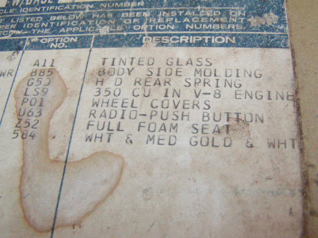
À A11 TINTED GLASS This is very nice.
À B85 BODY SIDE MOLDING This referrers to the upper trim along the sides. I should have noted that this option or option BX2 also includes a bright metal gas cap. With no side trim, the gas cap was the same a the body color.
À G50 H D REAR SPRING This is the heavy duty rear springs, capacity 2000 lbs each, thus bumping the GVWR up from the base 4400 lbs to 5000 lbs.
À LS9 350 CU IN V8 This option includes the emblems on the front fenders that say ô8-350ö. The 350 V8 is the most recognized Chevrolet engine ever built.
LS9 Details:
350 cu. in V8
Rochester 4MV carburetor (Quadrajet)
9.0:1 compression ratio
255 HP gross @ 4600 rpm
200 HP net @4000 rpm
355 ft-lbs gross @ 3000 rpm
310 ft-lbs net @ 2400 rpm
À P01 WHEEL COVERS Standard equipment is a set of painted hubcaps that cover the center portion of the wheels, often known as "dog dishes" because of their resemblence to a dog food bowl. An upgrade that was included when body trim was ordered were chromed hubcaps that are otherwise identical. This option is referring to a stainless steel cover that snaps to and covers the entire painted wheel, and even has simulated "lug nuts" along the perimeter.
À U63 RADIO-PUSH BUTTON Delco AM and AM-FM radios with push-button tuning were available, but the list doesnÆt specify because factory installed AM-FM radios weren't available in trucks until 1971. At any rate, mine is AM and working.
À Z52 FULL FOAM SEAT This means I have the more comfortable foam-core seat instead of the standard full spring seat. Also nice because I have been in a truck with the spring seat that was worn such that the springs poked at you.
À 584 WHT & MED GOLD & WHT My glorious two-tone paint scheme. Please not that whatever your truckÆs body color is, all the metal inside your cab is going to be that color too. And white was the only second color used in the two-tone schemes until 1975.
Here is the specifications for a base model fitted only with standard
equipment.
Pickup and chassis-cab models
Air Cleaner: Oiled-paper element
Axle, Front: Independent; capacity 2500-lbs
Axle, Rear: Hypoid semi-floating type; ratio 3.73; capacity
3500-lbs
Bodies: Stepside pickup, model 04; Fleetside pickup, model 34; Chassis and cab only, model 03
Brakes, Service: hydraulic; self-adjusting; dual system. Sizes: front 11" x 2"; rear 11" x 2". Effective area: drum 276 sq. in; lining 167 sq. in.
Brake, Parking: Cable to rear wheels; area 83 sq. in.; foot operated
Bumper: Painted. All models: Front only.
Carburetor: CS10: single-barrel downdraft
CE10: two-barrel downdraft
Clutch: CS10: diameter 10"; area 100 sq. in.
CE10: diameter 11"; area, 124 sq. in.
Cooling: CS10: 1 1/4" radiator core, cross flow type; 446-sq-in area; 13-lb pressure cap
CE10: 1 1/4" radiator core, cross-flow type; 480-sq-in area, 13 lbs pressure cap
Controls & Instruments: Light switch, windshield wiper-washer switch; headlight beam control; speedometer; odometer; fuel gauge. Lights for generator, oil pressure, engine temperature, brake warning, direction signals and high beam indicator. Ignition switch with accessory position
Direction Signals: Class A; two front and two rear. Includes freeway lane-change position on switch & integral hazard warning switch
Engine: CS10: 250 Six; controlled combustion exhaust system
Gross horsepower....155 @ 4200 rpm
Net horsepower.......125 @ 3800 rpm
Gross torque, lb-ft...235 @ 1600 rpm
Net torque, lb-ft......215 @ 2000 rpm
CE10: 307 V8; controlled combustion exhaust system
Gross horsepower....200 @ 4600 rpm
Net horsepower.......157 @ 4000 rpm
Gross torque, lb-ft...300 @ 2400 rpm
Net torque, lb-ft......260 @ 2000 rpm
Exhaust System: Single, fully aluminized
Filter, Fuel: Plastic mesh in fuel tank
CS10: Paper type in carburetor
CE10: Sintered bronze in carburetor
Filter, Oil: Full-flow; 1-quart; throwaway type
Frame: 39,000-lb-test steel; section modulus 2.98
Fuel Pump: Single action
Generator: 37-amp Delcotron
GVW Plate: See GVW Selector
Heater & Defroster: Deluxe-Air
Lights & Reflectors:
03 models: Two headlights; two Class A front combination parking/direction signals; two Class A rear combination tail/stop/direction signals, two front side marker combination lights & reflectors, two backup; one license; instrument panel & dome
04 & 34 models: Same as 03 models plus two rear side marker combination lights & reflectors
Mirror, Rearview: Exterior RH & LH 6 1/4" fixed arm and inside 10" vinyl-edged prismatic
Seat: All models; full-width; vinyl trim
Seat Belts: Includes retractors; all models; driver and passenger
Shock Absorbers: Front & rear; piston diameter 1"
Springs, Front: Coil; capacity 1250-lb each
Springs, Rear: Coil, capacity 1250-lb each
Steering: Ball-gear, ratio 24:1; wheel, oval 17 1/2" x 17", 2-spoke
Tank, Fuel: All models-back of seat in cab; capacity approx 21 gallons
Tires: Five bias-belted tubeless G78-15-B front, single rear and spare
Tools: 2500-lb mechanical jack; wheel wrench
Transmission: 3-speed fully synchronized; steering column gearshift; ratios 2.85, 1.68, 1.00, 2.95 (rev)
Wheels: Five 15" x 5 1/2"; attachment, 6 studs on 5 1/2" circle; spare carrier under frame; 4 painted hubcaps
Windshield Wipers & Washer: Electric; 2-speed wipers
|
GVW Rating (lb) |
Chassis Equipment Required for GVW Rating |
|
4400 |
Standard |
|
5000 |
2000-lb ea rear spring |
|
5400 (05 models only) |
1350-lb ea front spring 2000-lb ea rear spring |
Series
C10
|
ENGINE |
TRANSMISSION |
AXLE RATIOS |
|
|
STD |
OPT |
||
|
250 Six 292 Six |
Chevrolet 3-Speed |
3.73 |
3.07; 4.11 |
|
Chevrolet CH465 4-Speed |
3.73 |
3.07; 4.11 |
|
|
New Process 435CR 4-Speed |
3.73 |
3.07; 4.11 |
|
|
Powerglide |
3.73 |
4.11 |
|
|
Turbo Hydra-matic |
3.73 |
3.07; 4.11 |
|
|
307 V8 |
Chevrolet 3-Speed |
3.73 |
3.07; 4.11 |
|
Chevrolet CH465 4-Speed |
3.07 |
3.73; 4.11 |
|
|
New Process 435CR 4-Speed |
3.73 |
3.07; 4.11 |
|
|
Powerglide |
3.73 |
4.11 |
|
|
Turbo Hydra-matic |
3.07 |
3.73; 4.11 |
|
|
350 V8 |
Chevrolet 3-Speed H.D. |
3.07 |
3.73; 4.11 |
|
Chevrolet CH465 4-Speed |
3.07 |
3.73; 4.11 |
|
|
New Process 435CR 4-Speed |
3.07 |
3.73; 4.11 |
|
|
Powerglide |
3.07 |
3.73; 4.11 |
|
|
Turbo Hydra-matic |
3.07 |
3.73; 4.11 |
|
|
400 V8 |
Chevrolet 3-Speed H.D. |
3.07 |
- |
|
Chevrolet CH465 4-Speed |
3.54* |
- |
|
|
New Process 435CR 4-Speed |
3.54* |
- |
|
|
Turbo Hydra-matic |
3.07 |
- |
|
*Dana rear axle used with 400 V8
A combination Gross Vehicle Weight (GVW) and serial number plate is used on
1970 Chevrolet trucks. It is attached to the upper left-hand door pillar on
most cab models. The number consists of alpha and numeric characters
designating the chassis, engine, series (GVW range), model, model year,
assembly plant, and assembly sequence number.
|
First Digit: Identifies the Chassis |
|
|
Chassis |
Code |
|
Conventional Cab |
C |
|
|
K |
|
Second Digit: Identifies the engine |
|
|
Engine |
Code |
|
8-cylinder |
E |
|
6-cylinder |
S |
|
Third Digit: Identifies the GVW range |
|
|
|
Code |
|
3900-5800 lbs |
1 |
|
5200-7500 lbs |
2 |
|
6600-14,000 lbs |
3 |
|
Fourth and Fifth Digits: Identify the cab-to-axle dimension |
|
|
Cab-to-axle dimension |
Code |
|
30-35" |
05 |
|
54-59" |
09 |
|
60-65" |
10 |
|
84-89" |
14 |
|
Sixth and Seventh Digit: Identifies the body |
|
|
Body |
Code |
|
Chassis-cowl |
02 |
|
Chassis-cab |
03 |
|
Stepside pickup |
04 |
|
Panel |
05 |
|
Suburban (rear doors) |
06 |
|
Utility |
14 |
|
Suburban (tail & liftgate) |
16 |
|
Fleetside pickup |
34 |
|
Eigth Digit: Identifies the model year (1970) |
|
|
Ninth Digit: Identifies the assembly plant |
|
|
Assembly Plant |
Code |
|
Lakewood/Atlanta, GA |
A |
|
|
B |
|
|
F |
|
|
Z |
|
|
J |
|
|
P |
|
|
S |
|
|
T |
|
|
1 |
|
Last Six Digits: Represent the basic production number |
|
À 67-72chevytrucks.com, the message boards for 1947-1998 Chevy & GMC trucks, has a section for 67-72 models only.
À The Chevrolet Longhorn Truck Page, check out the 1968 50th anniversary trucks, they have a gold-and-white scheme much like mine's.
À The Stovebolt Page has lots of useful info and photo galleries, as well as a focus on all Chevy & GMC trucks from 1918 to 1972.
Technical & Tuning Related
Questions
or Comments? Send Email
Back
to the Main Page