9 Tube Stereo Amplifier
20 Watts per channel Maximum
Want big tube room filling sound without the trouble or expense of big tube equipment? Look no further! This 9 tube amp is simple to operate, powerful, and uses only 3 types of tubes. This amp features a 6BQ5 push-pull output for each channel, and two quiet, reliable 6EU7 tubes in each channel as well. A 5U4-G keeps plenty of power flowing. You have complete control with powerful bass and treble tone controls, and a balance control compensates for any speaker/room or source audio deficiencies.
Schematic:

The Magnavox-style output section uses a paraphase inverter and a minimum of circuit components. An inverse feedback loop minimizes distortion to give you clean, room filling tube sound. This is a powerful amplifier, if you live in a dorm room or small apartment, you may have difficulty, as this amplifier does not like to play at low volume levels.
Parts List
|
Control Resistors |
|
|
|
Resistor ID |
Value (ohms) |
Function, Notes |
|
R1A & B |
Dual-section 500K audio taper 1/2W |
Volume Control |
|
R2A & B |
Dual-section 1M linear taper 1/2W |
Bass Control |
|
R3A & B |
Dual-section 1M linear taper 1/2W |
Treble Control |
|
R4 |
750 linear taper 1W |
Balance Control *See note at end of parts list. |
|
Fixed Resistors |
|
|
|
R5, R23 |
2.2K 1/2W |
Input amp cathode |
|
R6, R24 |
220K 1/2W |
Input plate load |
|
R7, R25 |
10K 1/2W |
Bass tone comp |
|
R8, R26 |
100K 1/2W |
Bass tone comp |
|
R9, R27 |
100K 1/2W |
Audio coupling |
|
R10, R28 |
2.7K 1/2W |
Tone amp cathode |
|
R11, R29 |
82K 1/2W |
Tone amp plate load |
|
R12. R30 |
470K 1/2W |
Grid load |
|
R13, R31 |
47K 1/2W |
Grid input |
|
R14, R32 |
5.6K 1/2W |
Inverter cathode |
|
R15, R33 |
2.2K 1/2W |
Driver cathode |
|
R16, R34 |
220K 1/2W |
Plate load |
|
R17, R35 |
220K 1/2W |
Plate load |
|
R18, R36 |
220K 1/2W |
Output grid |
|
R19, R37 |
39K 1/2W |
Inverter grid |
|
R20, R38 |
470K 1/2W |
Output grid |
|
R21, R39 |
220K 1/2W |
Monitor isolation |
|
R22, R40 |
3.9K 1/2W |
Feedback coupling |
|
Power Resistors |
|
|
|
R41 |
100 10W wire wound |
Output cathodes |
|
R42 |
10K 5W wire wound |
Voltage divider |
|
R43 |
33K 2W metal oxide |
Voltage Divider |
|
R44 |
750 5W wire wound potentiometer |
Hum adjust |
|
Fixed Capacitors |
|
|
|
Capacitor ID |
Value |
Function, Notes |
|
C1, C10 |
0.047mF 630V |
Audio coupling |
|
C2, C11 |
0.002mF 630V |
Bass tone comp |
|
C3, C12 |
0.02mF 630V |
Bass tone comp |
|
C4, C13 |
0.0002mF 630V |
Treble tone comp |
|
C5, C14 |
0.002mF 630V |
Treble tone comp |
|
C6, C15 |
0.047mF 630V |
Audio coupling |
|
C7, C16 |
100mmf 630V |
B+ decoupling/snubber |
|
C8, C17 |
0.0047mF 630V |
Audio coupling |
|
C9, C18 |
0.047mF 630V |
Audio coupling |
|
C19 |
0.01mF 1400V |
Line bypass |
|
Electrolytic Capacitors |
|
|
|
C20 |
22mF 25V |
Cathode bypass |
|
C21 |
47mF 450V |
Filter |
|
C22 |
33mF 450V |
Filter |
|
C23 |
10mF 450V |
Filter |
|
C24 |
33mF 450V |
Filter |
|
Choke ID |
Inductance (henries @ 1000 cps) |
Current, notes |
|
L1 |
1 henry |
130 ma @ 330 volts, U-bracket |
|
Power Transformer, T1 |
|||
|
Primary |
Sec. 1 |
Sec. 2 |
Sec.3 |
|
117V AC 60cps .92A |
600V CT 130ma |
5 volts 3 amps |
6.3 volts 4 amps |
|
Output Transformers T2, T3 |
|
|
Primary Impedance |
Secondary Impedance |
|
8000 ohms,CT @ 400 cps |
Matched to speakers, with a tap @ 4 ohms for feedback. |
|
Miscellaneous Parts |
|
|
|
Part ID |
Description |
Function, Notes |
|
SW1A & B |
2-pole, 6-throw make-before break switch |
Audio Selector Switch |
|
SW2 |
Single-pole, single-throw switch, 5A rated |
Power Switch |
|
V1 |
6EU7 |
Input amp-tone amp left channel |
|
V2 |
6EU7 |
Driver-phase inverter left channel |
|
V3 |
6EU7 |
Input amp-tone amp right channel |
|
V4 |
6EU7 |
Driver-phase inverter right channel |
|
V5 |
6BQ5 |
Output left channel |
|
V6 |
6BQ5 |
Output left channel |
|
V7 |
6BQ5 |
Output right channel |
|
V8 |
6BQ5 |
Output right channel |
|
V9 |
5U5-G |
Current rectifier |
*Note on balance control: If you want to omit this balance control, such as when using separate pots for the volume controls, see the balance control notes on the 7-tube output amplifier page.
Reader's Contributions
Newest contributions on top.
George in Ohio
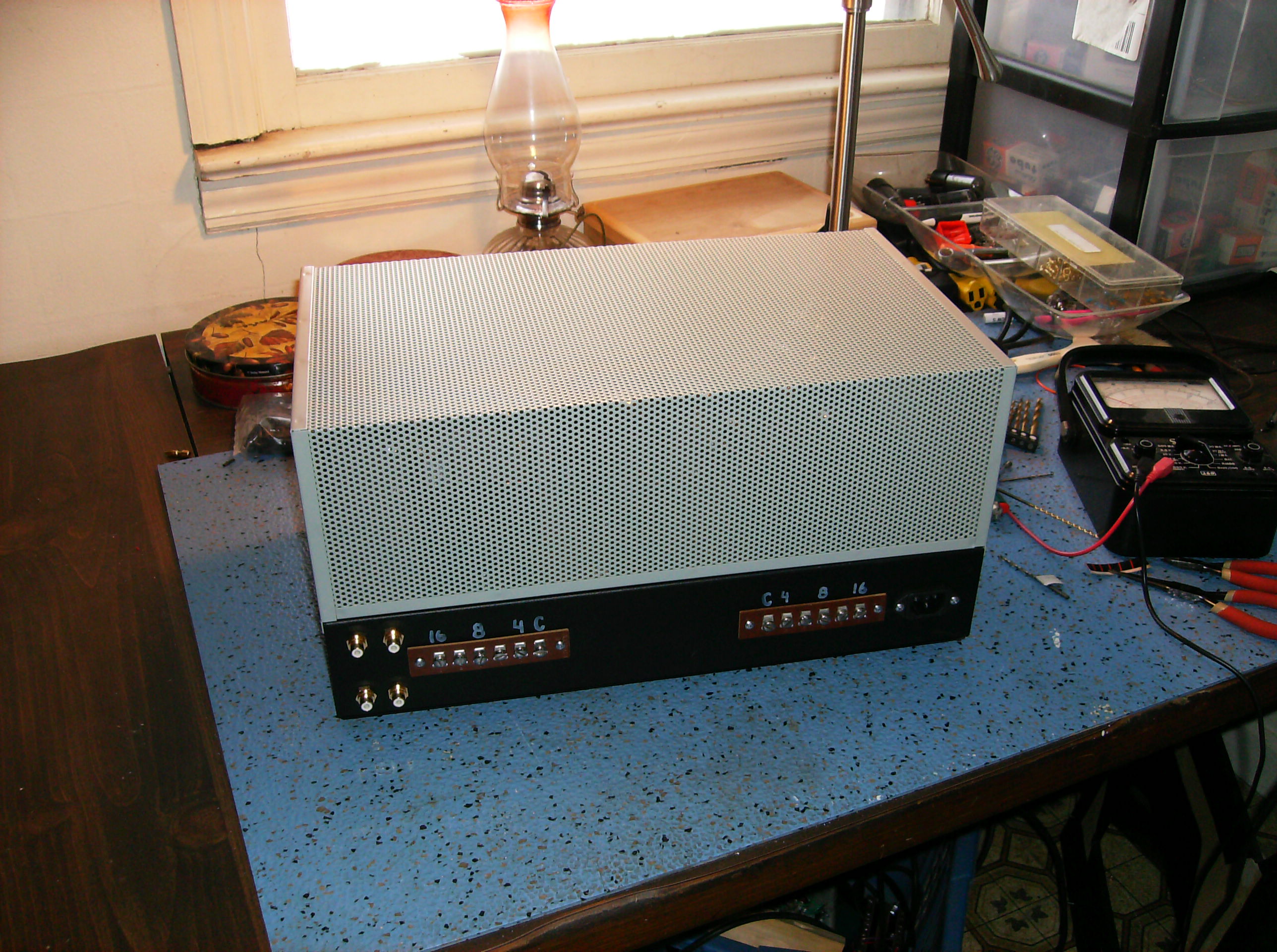
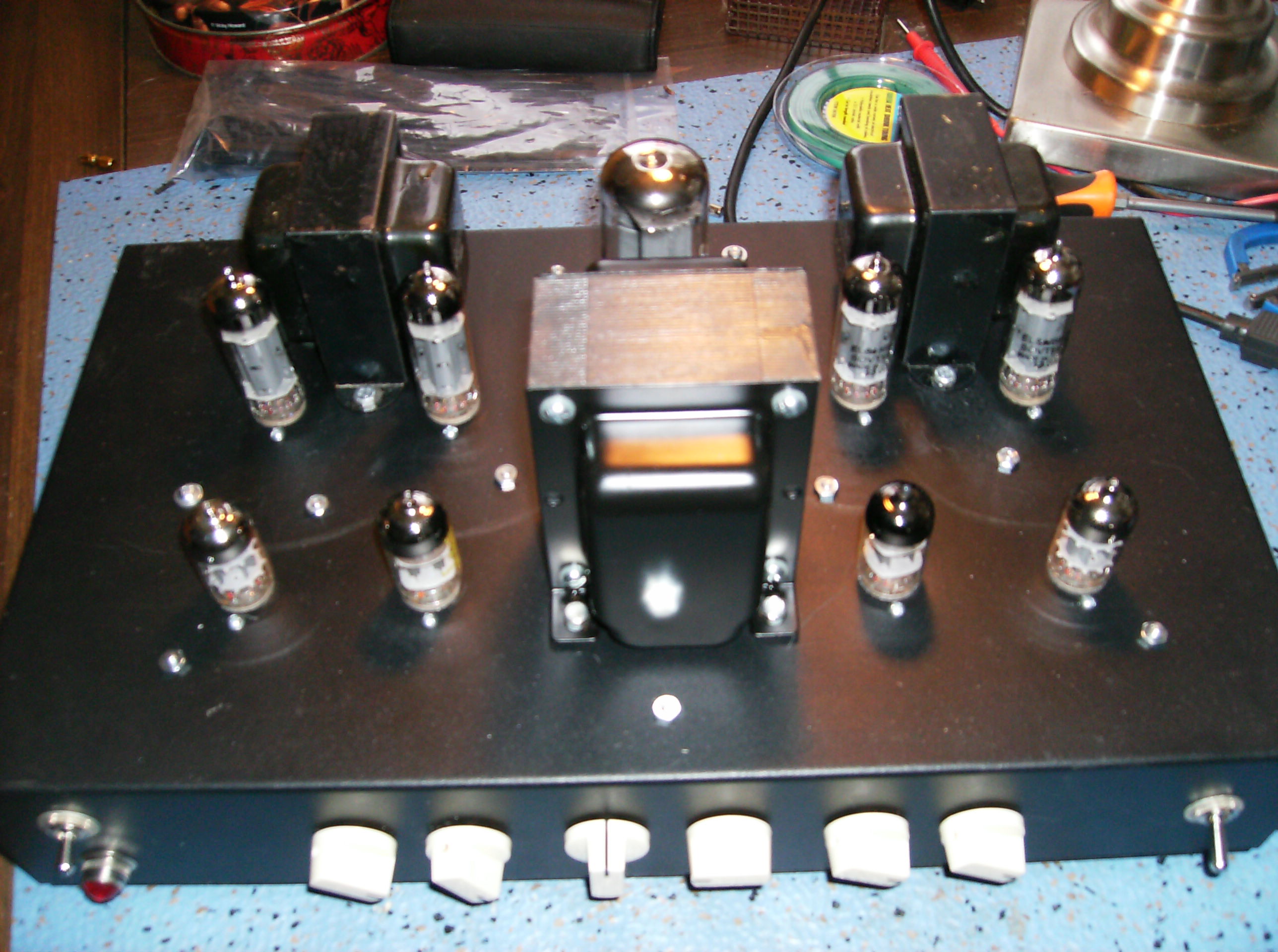
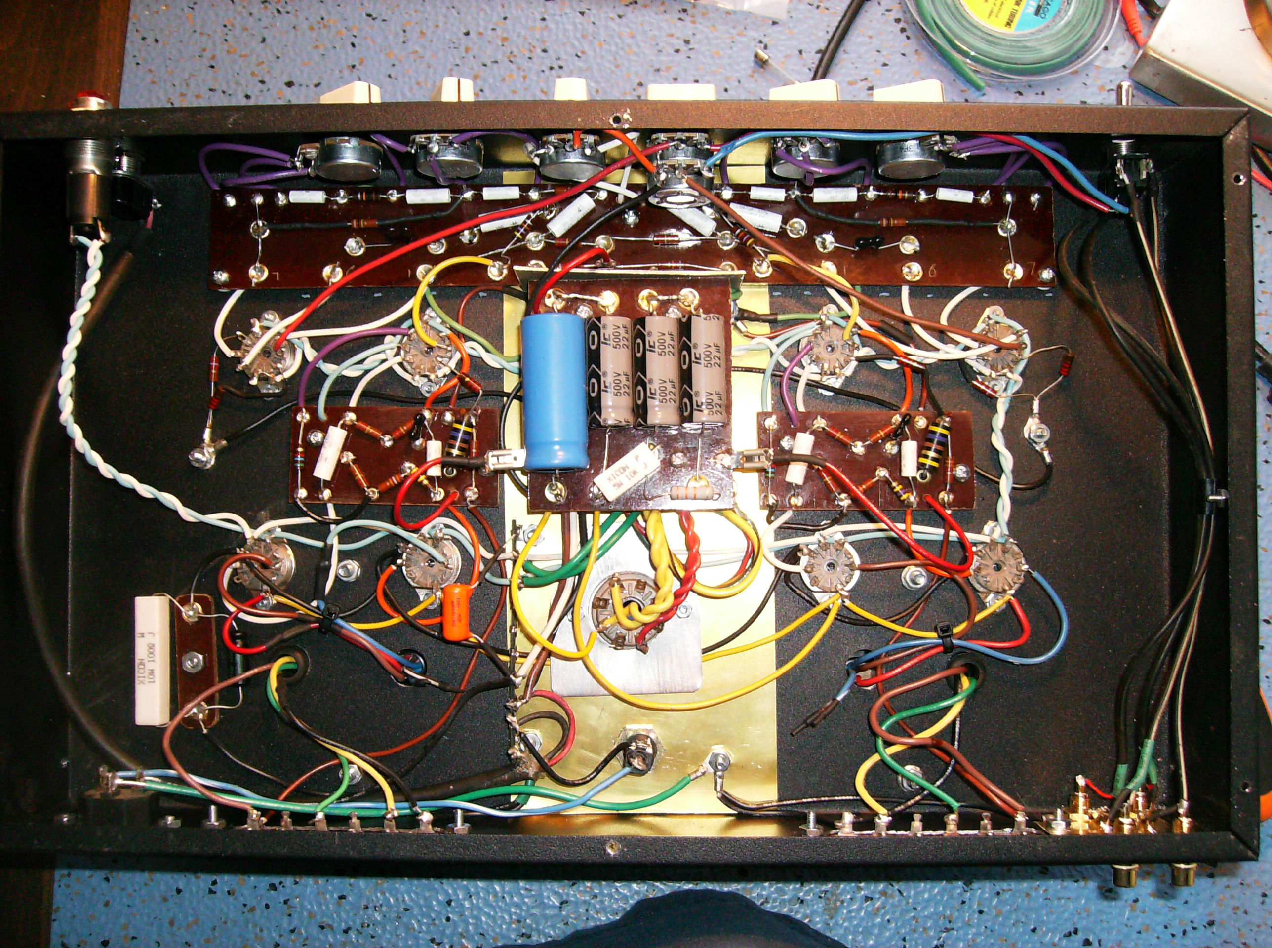
1-27-14 George emailed me photos of his amp and this note:
"Wes, I used the schematic posted on your site, and built this. modified slightly with separate bass and treble on each channel. also, I moved the location of the balance control in the circuit, to lessen the load on the pot. I gave it two sets of switchable inputs. I used handmade parts boards. (similar to a fender) at this point I was testing it out. sounds very nice. I'm driving it with a Grundig Yacht Boy 300. I have to go back in to add the filter choke. I was anxious to try it out."
As You can see from the photos, George did a nice job with chassis layout, and has just done a real first-class job with the layout and construction. The silver top cage gives the finished rig a nice "classic" look.

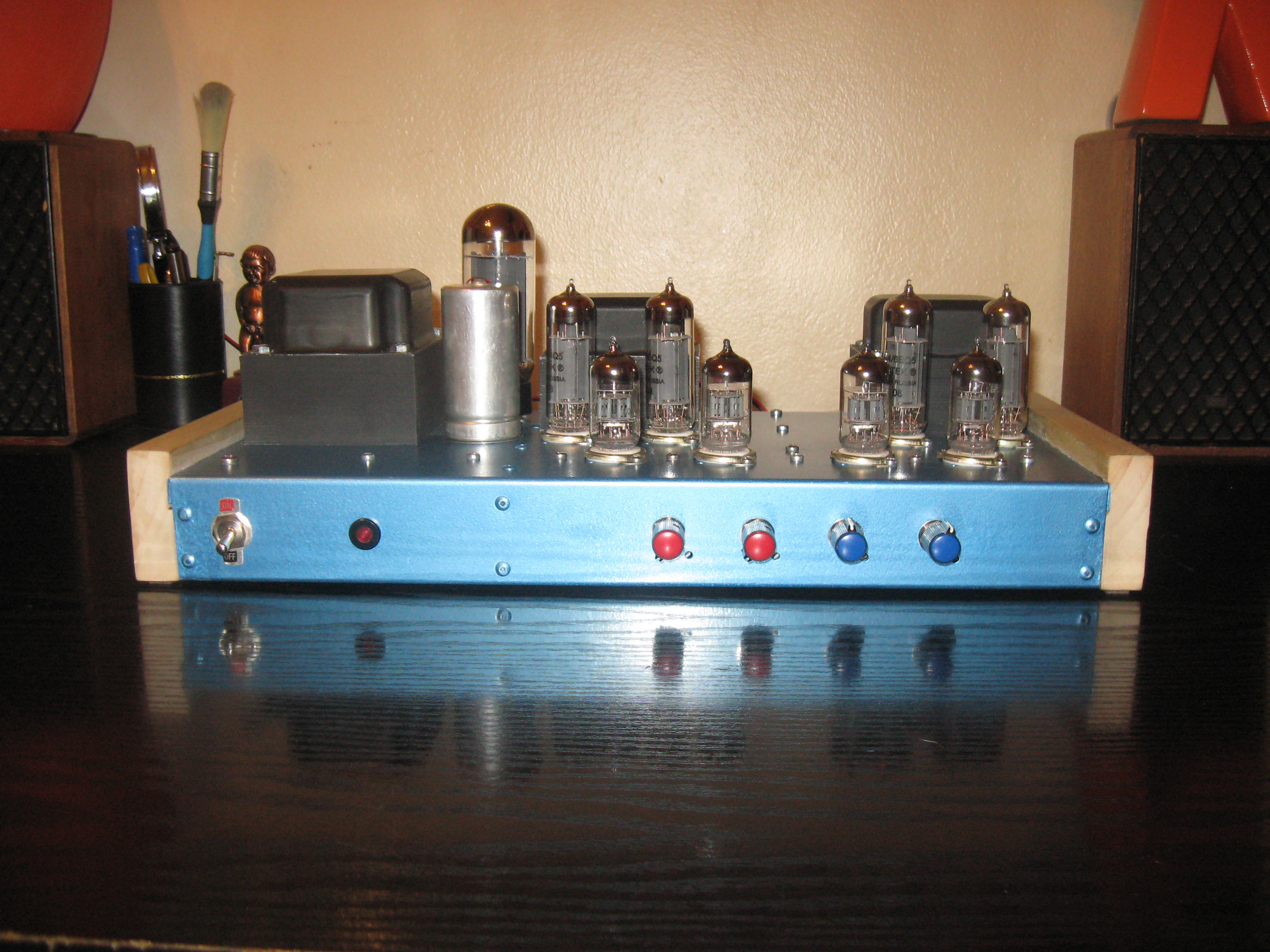
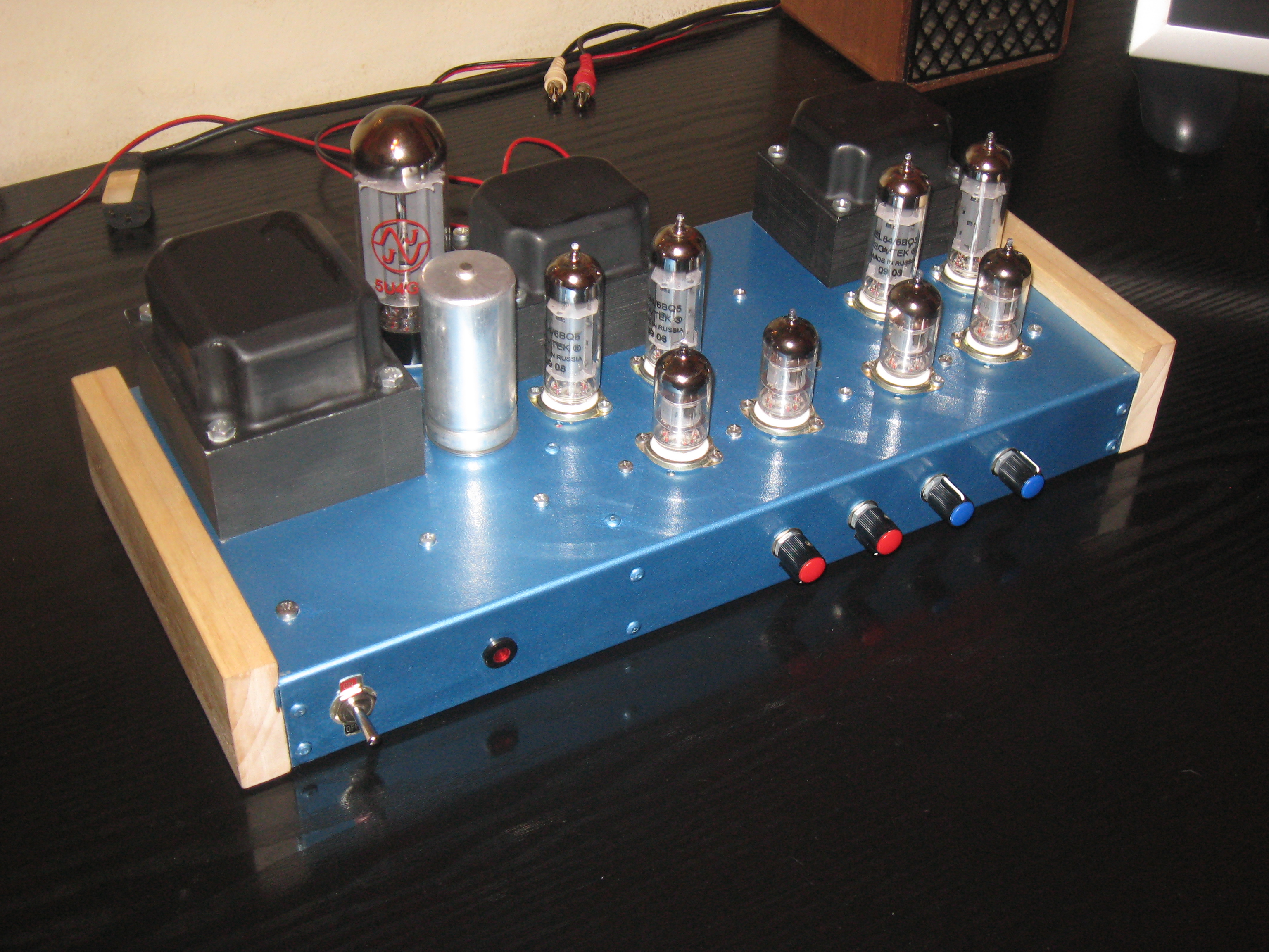
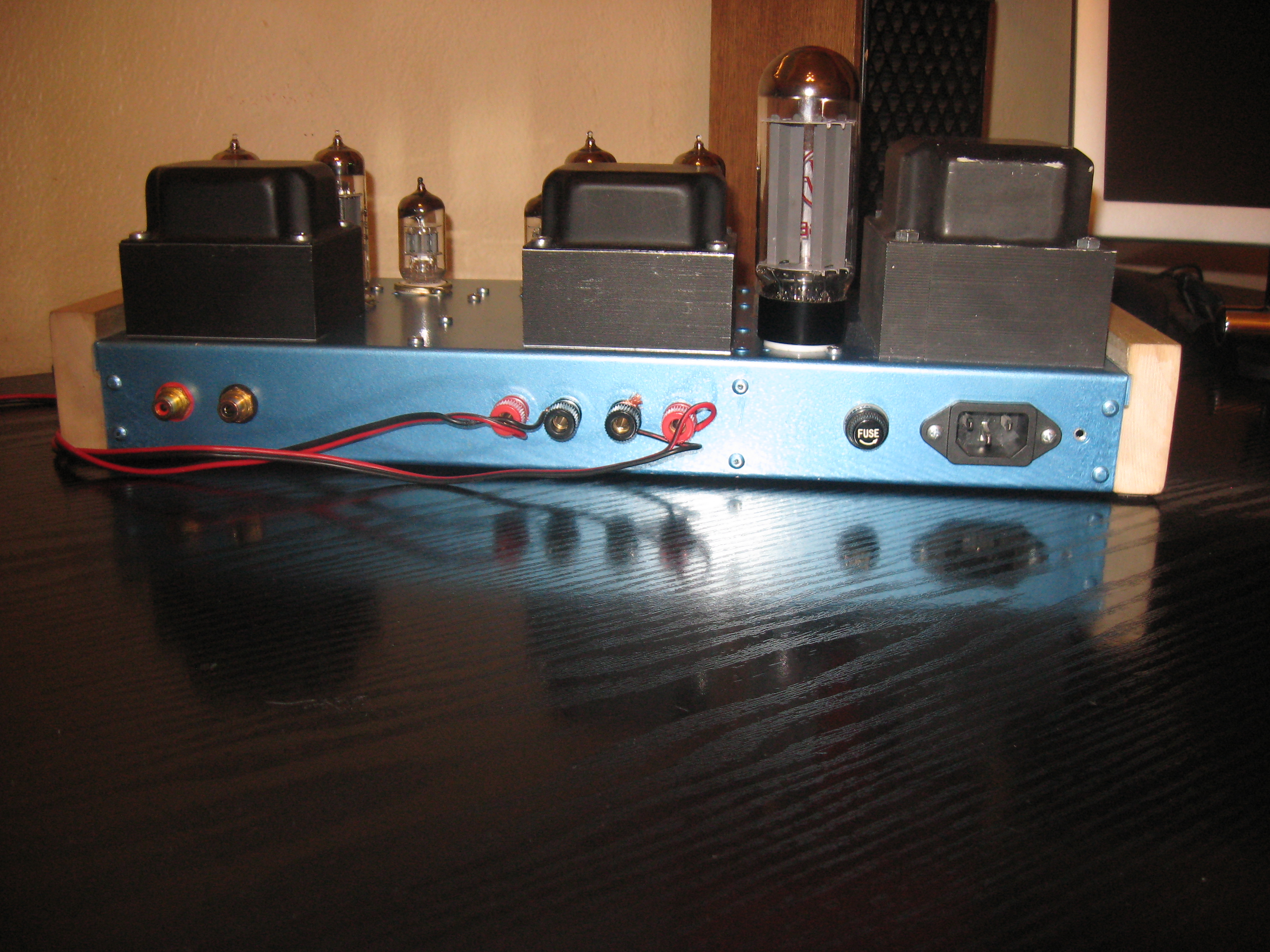
DC Stelios
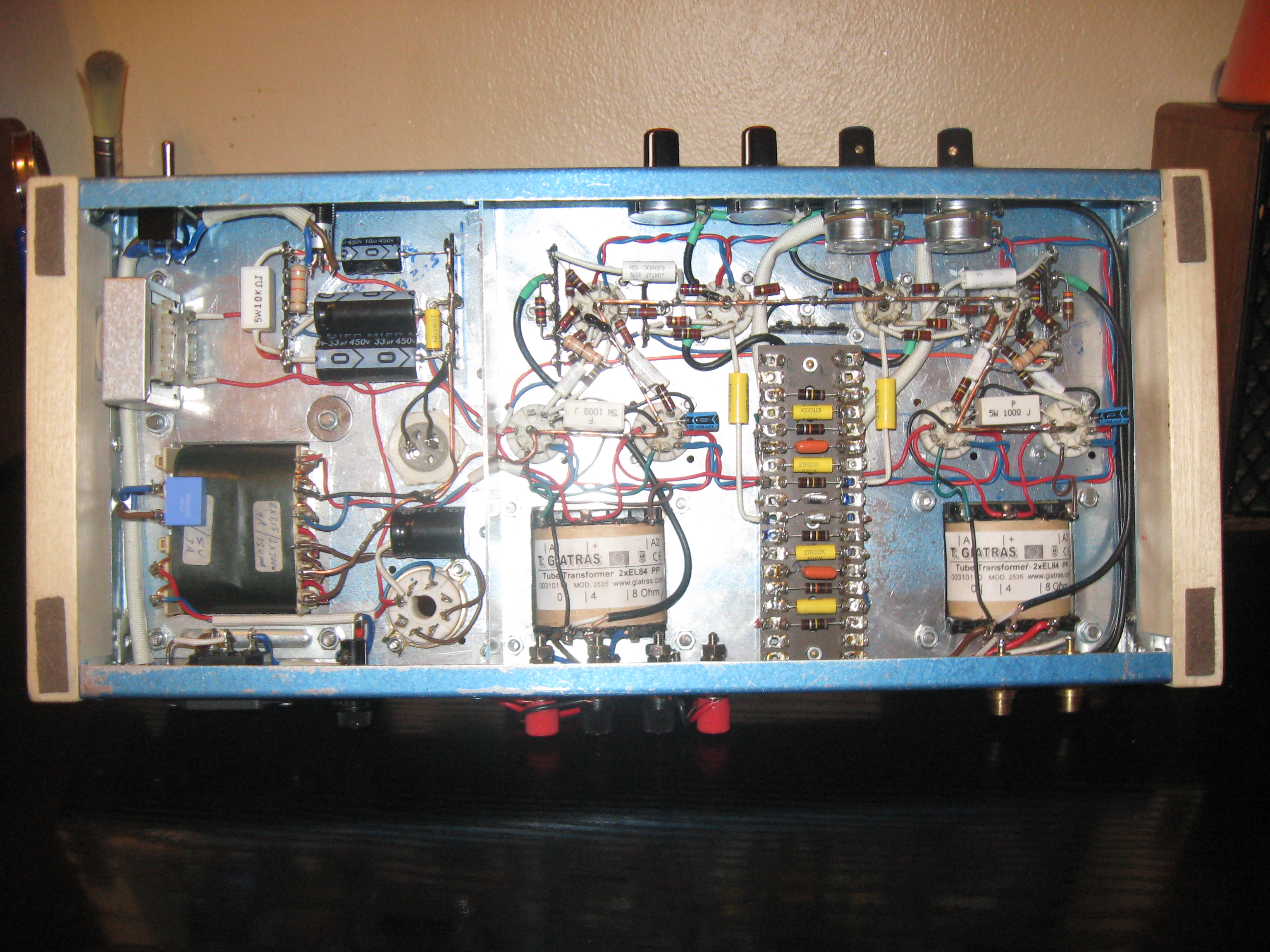
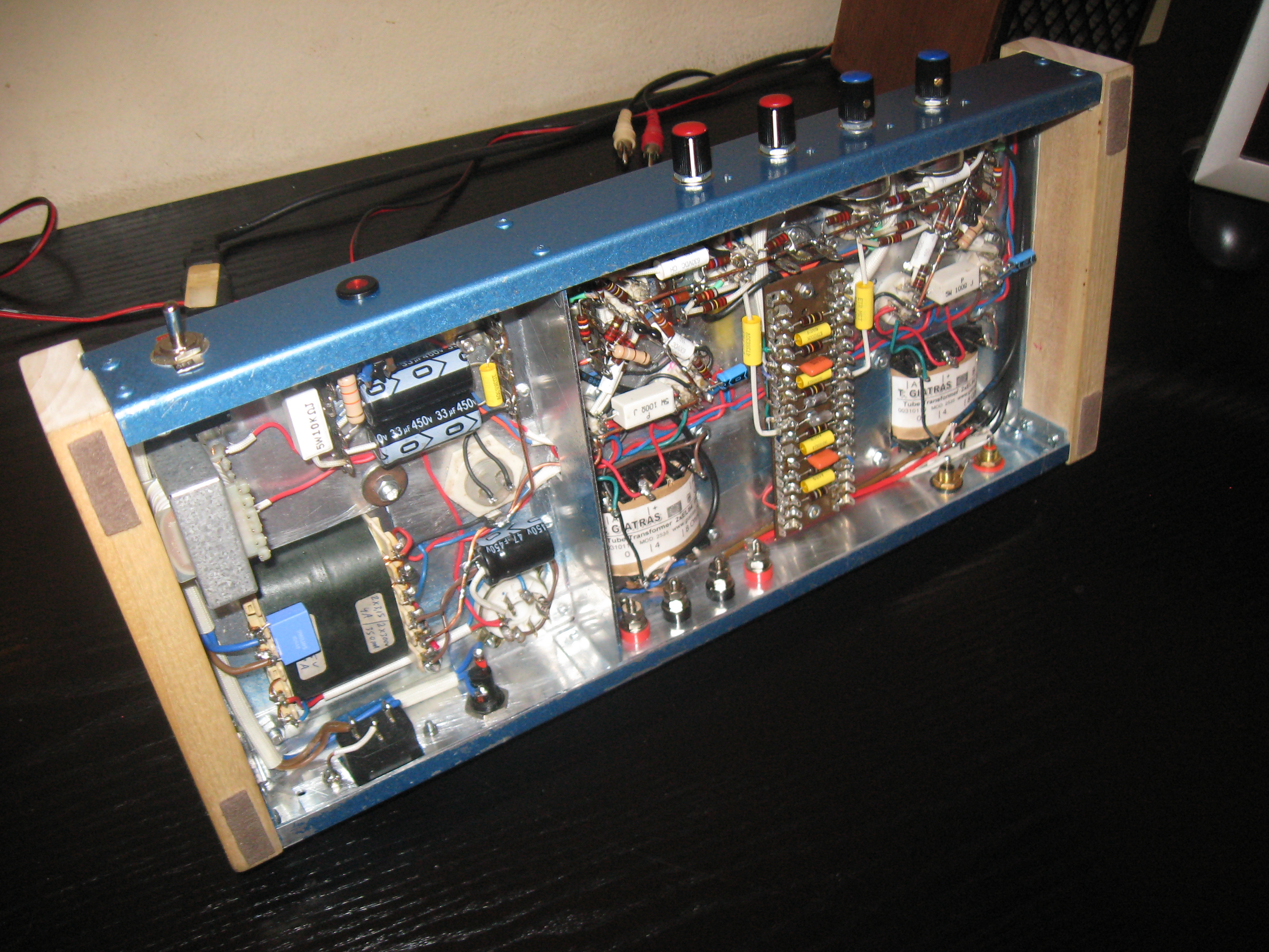
1-25-12 DC has written me several times with questions and comments about this schematic and was kind enough to share a few photographs of the amplifier he built from it. He has told me it sounds as good as it looks, and I believe it. DC did not use a commercially made chassis box, but built it himself and the results are very nice with the layout, color finish and wood ends. Also note the shielding partition DC built between the power supply and amplifier stages. DC chose the asymmetrical chassis layout you see here for minimal hum. Note the very clean layout that DC designed for the circuit components in the chassis underside views. DC has been very picky about component and interconnect lead dress, and I believe it has paid off in the amp's performance.
Click on any picture to enlarge
If you too have built this amp, then email me a few pictures if you like, and I'll add them here with a few comments. Just email them to the address shown in the contact info on the Radio Page in the link below.
Created 11-21-09
Back to the Radio and Electronic Page.