|
|
|
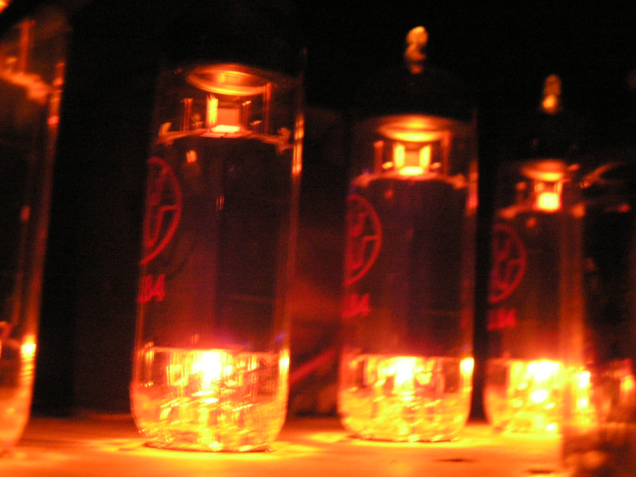
There's nothing finer that listening to beautiful music while watching the tubes glow in a darkened room |
This is a 7 tube 20 watt amplifier that must be used in conjunction with a pre amplifier having volume an tone controls. For this, I recommend this 6 tube pre-amp. With this amplifier you may use 6BQ5 output tubes. A 5U4-G rectifier is used so that the power supply will have plenty of pep to run the amp. This amplifier is basically a Magnovox amplifier I bought on ebay years ago and rebuilt after building the 6 tube amp. It is really amazing how it sounds, and the circuit is very minimalist, as you can see. Because of the output setup, you must use a quartet of matched 6BQ5 tubes.
|
|
|
There's nothing finer that listening to beautiful music while watching the tubes glow in a darkened room |
I have noticed, using speakers with 12"-4"-2" sizes, that this is really bottom heavy, even with the preamp tone controls set for flat reproduction.
You will notice in looking at the schematic my preference for the balance control. I find this a convenient way to compensate for less than optimal speaker placement in my living room
Schematic:
Read the notes in the parts list on the balance control.

Above, the amplifier's schematic. In addition to the 6BQ5 output tubes, a 6EU7 dual-triode is used in each channel. This amplifier also uses a curious phase-inverter circuit I have heard described as a "paraphase" inverter.
Parts list
| Resistor ID | Value | Function, notes |
| R1, R15 | 470K 1/2W 5% | Input load |
| R2, R16 | 47K 1/2W 5% | Input isolation |
| R3, R17 | 2200 1/2W 2% matched | Cathode |
| R4, R24* | 330 1/2W 2% matched | Fixed balance, omit when using balance control R25. See note at R25 |
| R5, R18 | 5600 1/2W 5% | Cathode |
| R6, R19 | 39K 1/2W 5% | Grid-leak voltage divider |
| R7, R14 | 220K 1/2W 5% | Plate load |
| R8, R22 | 470K 1/2W 5% | Grid-leak voltage divider |
| R9, R23 | 3900 1/2W 5% | Feedback isolation |
| R10, R21 | 220K 1/2W 5% | Grid leak |
| R11, R20 | 220K 1/2W 5% | Plate load |
| R12 | 100 ohms 5 watts W.W. | Output cathode |
| R13 | 750 ohm pot, 5 watts | hum adjust |
| R25* | 750 ohm pot, 1/2 watt linear taper | left-right balance control. Omit R4 and R24 when using the balance control. * See Note |
| R26 | 10K 5 watts | filter |
*Note R4 and R24, optional fixed balance control, omit 750 ohm 1/2 watt pot. The original balance control was mounted inside the tuner. When I began using this amplifier without the tuner, I had to add two resistors in place of the connections to the pots. For whatever reason, I installed two 330 ohm resistors and used the amp this way for years before the rebuilding when I added a balance control pot. I was lucky to find a pot with the same value as the original at a real electronics parts store. Many readers have emailed saying they are having difficulty finding a 750 ohm pot. If this is the case for you, just omit the pot and use the 330-ohm resistors as shown.
| Capacitor ID | Value | Function, notes |
| C1, C4 | 100mmF 500V | AF plate, silvered mica |
| C2, C5 | .0047mF 630V | AF coupling, metalized polyester |
| C3, C6 | .047mF 630V | AF coupling, metalized polyester |
| C7 | .01mF 1400V | Line bypass, ceramic |
| C8 | 10mF 450V | Filter, electrolytic |
| C9 | 33mF 450V | Filter, electrolytic |
| C10 | 47mF 450V | Filter, electrolytic |
| C11 | 20mf 25V | Output cathode bypass, electrolytic |
Note: When the schematic was redrawn, it was discovered that C1 and C4 were shown in the incorrect location. They should connect pin 7 of each 6EU7 to ground, and not pin 8 as was shown on the old version.
| Choke ID | Inductance (henries @ 1000 cps) | Current, notes |
| L1 | 1 henry | 130 ma @ 330 volts, U-bracket |
| Power Transformer, T1 | |||
| Primary | Sec. 1 | Sec. 2 | Sec.3 |
| 117V AC 60cps .92A | 600V CT 130ma | 5 volts 3 amps | 6.3 volts 4 amps |
| Output Transformers T2, T3 | |||
| Primary Impedance | Primary DC resistance | Secondary Impedance | Secondary DC resistance |
| 8000 ohms,CT @ 400 cps | 300 ohms total | 4 ohms @ 400cps* | 0.3 ohms # |
* Match to speakers you are using, but it is preferable that the feedback connection go to a 4 ohm output as shown. # May be different if your impedance is not 4 ohms.
Tube line-up:
Notes:
Updated 11-20-09
Back to The Radio & Electronics Page