
This is a pre-amp which I have most recently finished constructing. It features 4 selectable line-level stereo inputs, a ceramic phonograph input with proper equalization for most American LP and 45 recordings for the convenience of most automatic record changers, and a magnetic phonograph input so that full advantage of the increased fidelity of better quality turntables may be enjoyed. The mag phono input has 3 selectable equalization characteristics to comply with the various standard recording curves encountered, as well as no compensation for odd recordings and 78's:
LP, RIAA
Audio Engineering Society
Foreign
No Compensation
Separate bass and treble controls have also been provided to adjust the overall characteristic of the music being listen to. The performance of this amplifier has been evaluated from several sources and all seem to confer that the qualities of this design are outstanding and that the design is a good one for more advanced builders as well as seasoned beginners (by that statement, I mean me. I have never build a radio from scratch until this, however, I have recapped a few old TV's and radios.)
The chassis for this amp is a 16 gauge steel box measuring 6 inches by 10 inches by 2 inches tall. Traditional point-to-point wiring techniques were used exclusively. Because modern components such as resistors and capacitors are so much smaller than they were at the height of the tube era, a very efficient circuit layout was possible. I used metalized polyester capacitors for larger values, silvered mica capacitors for smaller values, and carbon composition resistors for all 1/2 watt resistors. The result is an amplifier with a superbly rich tube sound, very detailed and clear.
Recommended output amplifier.
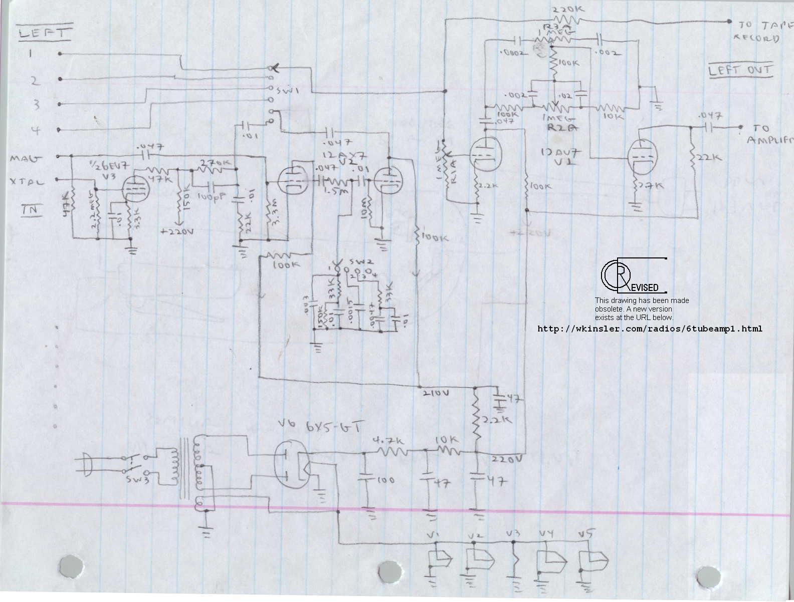
The schematic is reproduced here, showing the power supply and the left channel only. The right channel is identical in every respect, so showing its circuit is not necessary. The schematic was redrawn from the original schematic by a site visitor, Mario C. de Zuniga, whom I thank dearly for doing so. I have added part ID's to key with the parts list tables given further in this document.
The power transformer is 117v @ .5A primary, 500v CT @60ma secondary 1, and 6.3v @ 2.5A secondary 2.
Capacitors in the power supply are rated to 450 volts and the 4.7k power resistor is 5 watts wire wound. The 10K power resistor is 2 watts metal oxide, and the 2.2K power resistor is also 2 watts metal oxide.
Volume control is R1. Bass is R2, treble is R3.
Tubes used:
V1 12AU7 left AF amp
V2 12AX7 left mag phono amp
V3 6EU7 left and right ceramic phono amp
V4 12AU7 right AF amp
V5 12AX7 right mag phono amp
V6 6X5-GT Rectifier.
Photos:
Photos taken February 2005. The amp was built in January 2003.
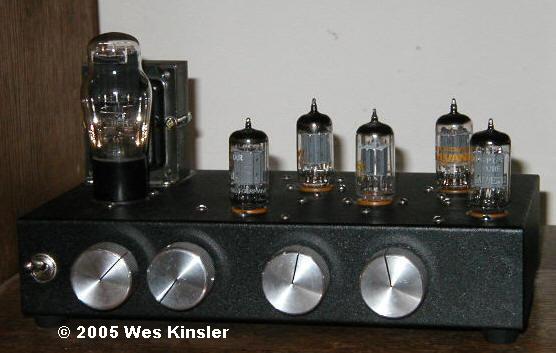

Left, view from the front. The controls are, from left to right: on-off, volume, bass, and treble. Right, underside view. The thick black wires are shielded connectors. The inputs, mag phono EQ selector, and outputs are arranged in that order across the back, with the right channel jacks in the bottom row. All component leads are short and direct. I built everything in layers, laying out the design full-size on paper first. Once all the locations of the transformer, tube sockets, and terminal strips was finalized, I re-drafted everything, and then made several full-size photocopies. I then fixed one of the copies to the chassis and used it to center punch the locations of all holes to be drilled or punched.
Construction:
After finalizing the circuit design, I drew out sketched mock-ups of each of the nine sections of the amplifier. No components join in midair, all connections occur at a terminal strip lug, tube socket lug, switch lug, potentiometer lug, etc. I was able to arrange everything to use 3, 5, 6, and 8 lug terminal strips. The three lug strip was really a five lug strip with two lugs broken off. The 6 and 8 lug strips both have a lug at each end that doubles as grounding points, the five lug has just one ground lug. I then proceeded to laying out the design full-size on paper. After I was satisfied with the arrangement, I redrafted the drawings to show only the locations of all the parts that would require hole to be drilled for mounting. By doing this, I could have a full-size template to use when marking out where the holes should be drilled.
All hole locations were center punched first with the template first, then drilled for small holes, and punched for large holes. The paint was then ground off where the terminal strips, tube sockets, and jacks were to attach. Then the in/out jacks, tube sockets, transformer, and terminal strips were mounted.
The first wiring to be done was the power transformer leads, followed by all unshielded chassis wiring, such as B+, filament, and some audio leads. All this wiring was done with colored cloth wire; green for filaments, red for 220V B+,orange for 210V B+, white for left channel connections, and blue for right. All of these wires were kept close to the chassis.
Then the power supply was built and tested, followed by the left AF amp and tone controls (the components for the tone controls were soldered to the pots first, then the pots where installed in the amp), then the right channel. Each section was tested as built. When the left and right AF stages were done, I then installed the input selector. The shielded wires were soldered to the switch first, then it was installed in the amp. Afterwards, I build the xtal phono amp, and last, the mag amp. The connections to the mag phono EQ selector were done in the chassis.
Parts List:
This is the official list of parts for this amp
| Resistor ID | Value | Function, Notes |
| R1 | 2.2M 1/2 watt 5% | Input load NOTE: follow cartridge manufacture's recommendation for value of this resistor. |
| R2 | 47K 1/2 watt 5% | Input load NOTE: follow cartridge manufacture's recommendation for value of this resistor. |
| R3 | 3.3K 1/2 watt 5% | cathode |
| R4 | 47K 1/2 watt 5% | plate |
| R5 | 150K 1/2 watt 5% | plate load |
| R6 | 270K 1/2 watt 5% | tone comp. |
| R7 | 22K 1/2 watt 5% | tone comp. |
| R8 | 3.3M 1/2 watt 5% | grid leak |
| R9 | Omitted | Omitted |
| R10 | 100K 1/2 watt 5% | plate load |
| R11 | 150K 1/2 watt 2% | tone comp. |
| R12 | 33K 1/2 watt 2% | tone comp. |
| R13 | 1.5M 1/2 watt 5% | de-emphasis, coupling |
| R14 | 33K 1/2 watt 2% | tone comp. |
| R15 | 10 Meg 1/2 watt 5% | grid leak |
| R16 | 1.2K 1/2 watt 5% | cathode |
| R17 | 100K 1/2 watt 5% | plate load |
| R18A | 1 Meg audio taper | Volume control, 2-gang. R18B for right |
| R19 | 2.2K 1/2 watt 5% | cathode |
| R20 | 100K 1/2 watt 5% | plate load |
| R21 | 10K 1/2 watt 5% | Bass tone comp. |
| R22A | 1 Meg linear taper | Bass tone control, 2-gang. R22B for right |
| R23 | 100K 1/2 watt 5% | Bass tone comp. |
| R24 | 100K 1/2 watt 5% | tone comp. |
| R25A | 1 Meg linear taper | Treble tone control, 2-gang. R25B for right |
| R26 | 2.7K 1/2 watt 5% | cathode |
| R27 | 22K 1/2 watt 5% | plate load |
| R28 | 220K 1/2 watt 5% | monitor isolation |
| R29 | 4.7K W.W. 5 watts 10% | power supply filter |
| R30 | 10K metal oxide 2 watts 5% | voltage divider |
| R31 | 2.2K metal oxide 2 watts 5% | voltage divider |
Unless noted, resistors are carbon composition.
| Capacitor ID | Value | Function, notes |
| C1 | .01mF metalized polyester 630V | cathode bypass |
| C2 | .01mF metalized polyester 630V | tone comp. |
| C3 | 100pF silvered mica 500V | tone comp. |
| C4 | .01mF metalized polyester 630V | output coupling |
| C5 | .047mF metalized polyester 630V | input coupling |
| C6 | .047mF metalized polyester 630V | output coupling |
| C7 | .01mF metalized polyester 630V | tone comp. |
| C8 | .0015mF metalized polyester 630V | tone comp. |
| C9 | .0047mF metalized polyester 630V | tone comp |
| C10 | .01mF metalized polyester 630V | tone comp. |
| C11 | .01mF metalized polyester 630V | interstage coupling |
| C12 | .1mF metalized polyester 630V | output coupling |
| C13 | .047mF metalized polyester 630V | DC blocking |
| C14 | .002mF metalized polyester 630V | bass tone comp. |
| C15 | .02mF "orange drop" 630V | bass tone comp. |
| C16 | .0002mF silvered mica 500V | treble tone comp. |
| C17 | .002mF metalized polyester 630V | treble tone comp. |
| C18 | .047mF metalized polyester 630V | output coupling |
| C19 | 100mF electrolytic 450 volts | filter |
| C20 | 47mF electrolytic 450 volts | filter |
| C21 | 47mF electrolytic 450 volts | filter |
| C22 | 47mF electrolytic 450 volts | filter |
| C23 | .003mF metalized polyester 630V | tone comp. |
| Power Transformer T1 | ||
| Primary | Secondary 1 | Secondary 2 |
| 117V AC 60cps 0.5A | 500V, CT @ 60mADC | 6.3V @2.5 A |
| Switches | ||
| SW1 | 2-pole, 6 throw rotary selector switch, shorting type | |
| SW2 | 2-pole, 4 throw rotary selector switch, shorting type | |
| SW3* | 1-pole, 1 throw toggle switch, 5A-125VAC | |
| Miscellaneous | ||
| M1* | 1.0 Amp, 250 volt fast blow fuse | |
*Note: In the actual built version of this amp, I used a 2-pole, single throw toggle switch, and did not use a fuse.
Older version of this page:
Around the first of the year [Dec. 2002/Jan. 2003], I completed a new amplifier. It is a pre-amp designed to drive an old output amplifier. It is stereo, uses 6 tubes and has a few notable features.
Phono inputs:
Two phonograph inputs, one for magnetic pickups, and one for ceramic. The ceramic input allows me to use a record changer, which almost universally uses a ceramic pickup. A single triode section from a 6EU7 tube is used for each channel, and a fixed EQ curve is used that gives best results on most American LP pressings. Other types may be played properly by adjusting the tone controls
The other input is for the higher-quality magnetic pickup. Unlike the fixed EQ characteristic of the ceramic phono pre-amp, the mag stage has 4 selectable positions: 1. RIAA LP, 2. Audio Engineering Society, 3. European, and 4. no variation. This allows a wide range or recordings to be played properly. A 12AX7 tube is used in each channel, giving two stages boosting the mag imput to line level.
4 additional line level inputs are provided so that I may hook up several sources without additional switching.
A line out is also provided so I may record from any of the six sources.
Tone Controls:
Bass: A bass control is provided giving a 15db boost and 12 db cut for low frequencies around 140cps down. The control is a variable R-C network inserted between the audio-frequency (AF) stages.
Treble: Like the bass, this is also an R-C network inserted between the AF stages. 12db cut and 10db boost are possible fro frequencies about 12000cps and up with a rolloff on out to 20000cps.
In each case, the variable element is a 1-meg ohm pot.
Line Stage:
The main amplifier is the line stage that all six inputs pass through. Each channel has a 12AU7 and therefore, two amplifier stages. The volume control is in the grid circuit of the first stage, and the tone control network in the coupling circuit between the plate circuit and grid circuits of the first and second stage. Output of the second stage goes directly to the 'output to amplifier' jack through a DC blocking capacitor.
Power supply:
The power supply of this amplifier is highly filtered, and supplied by a 6X5-GT rectifier. Current is 60ma. The value of the capacitor in the input-capacitor type f filter network is
100mfd. Three additional capacitors of 47mfd each, separated by a dropping resistor, make up the rest of the power supply. The voltage availiable for the line and ceramic stages is 230 volts, the voltage for the mag stage is 210 volts.
Back to The Radio & Electronics Page