This is a 3-tube stereo amplifier that is good for a beginner, or a budget-conscious person. It is so easy to build that it could be assembled and playing in a half-hour with no problems at all! It has no bulky power transformer, and the minimal number of components in the signal path. It can also be built of scrap radio parts on a piece of metal or board measuring only 3" x 5"
Since it is just the bare bone essentials, this project would also be great for teaching/learning vacuum tube electronics fundamentals. You have two options with this project: build it with all new components for a dirt cheap, extremely simple homebrew that should work well, or have fun and make something with all those parts you've got laying around. The required parts for this amp can be found in any AA5 tube radio, though the 35C5 tubes were most commonly found in the old 7-tube table top AM-FM sets. Anyway, if you use used parts, you should be able to build a real tube amp for under $10.
Why order tubes when you can use up the ones you have laying around. Here are some subs you can use with this circuit:
These miniature tubes may be replaced with octal tubes if you prefer. Thus, use a 35L6-GT for each 35C5, and a 35Z4-GT in place of the 35W4. Tubes which lock in place (loctals) also exist, and can be used if desired. Octal and miniature tubes listed all have 150mA heaters, and can be used in combination.
The 35B5 my be used in place of the 35C5. The 35B5 has a different pinout, but otherwise is the same tube.
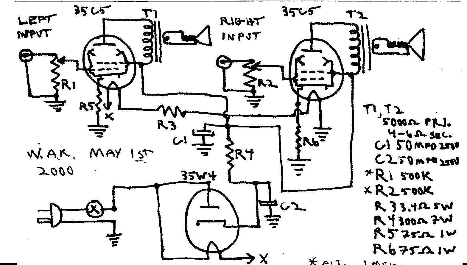
Please Note: R3 should actually be 34 ohms, not 3.4 ohms (unless you plan to operate this amp between 100-105 volts AC). With this value, it should work fine on 110VAC. For 115VAC, use 68ohms, and for 120VAC, use 100 ohms. Or, just make it "Universal" (105-125VAC or 100-120VDC) and use a resistor with a value near 113 ohms. For all values, R3 should be at least 5 watts
* R1 and R2 may be either 500k, audio taper; or 1 meg, audio taper. The choice is entirely up to you based on your input source.
Make sure that a polarized plug is used. Make sure that the neutral (wide) blade is connected to the chassis.
The output transformer (T1, T2) primaries are 5000 ohms, the secondaries should be matched to whatever your speaker impedance is going to be.
Use an appropriate socket for the tube you are using, and look over the base connections carefully when subbing tubes. I have not included base pin numbers so that this schematic can be easily read when using substitutes.
With its minimal parts list, this circuit invites you to make modifications, and hear how each one changes the amp's performance. You may want to increase the values of C1 and C2 to 80 or 100 mfd. Add a .0022mfd 600V capacitor across the primary of T1 and T2. Or add a 50mfd 25V bypass capacitor across R5 and R6.
You can add a very simple tone control using a .01mfd 600v capacitor and a 1 meg linear pot: connect one lead of the capacitor to the plate of the output tube. Connect the other lead to the middle terminal of the pot, and connect one of the end terminals to circuit ground (use only terminals of the pot). Experiment with different values of capacitor (caution against using anything larger than .08mfd).
Although not actually beginner orientated, Hot Rodding AA5 radios also deals with the idiosyncrasies of heater string tube sets, and may give some insights. Buy a few tube clock radios at a sale for $2-3 each and have fun!!!
Back to The Radio & Electronics Page