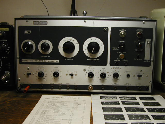
This device is the TV serviceman's best friend. It has a full array of features which allow a technician to quickly isolate a defect in a tube-type set to just one stage, or a few components in a stage. When used with an oscilloscope, it is a quick, accurate way to diagnose TV receiver defects.
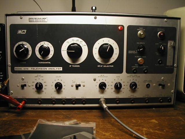
The above picture is my 1076 TV Analyst, with some of the paperwork that goes with it. On the left is the parts list/schematic, on the right is a chart of typical waveform traces. Below is a close view of the 1076.
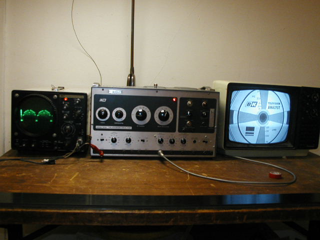
Like I said, the 1076 is a powerful tool for TV servicing. One thing it can do, which I shall display here, is the ability to generate test patterns and RF frequencies. The photo below shows the 1076 connected to a Black-and-white TV set thru its own RF generator. The scope, also by B&K, is connected to the 1076's video output.
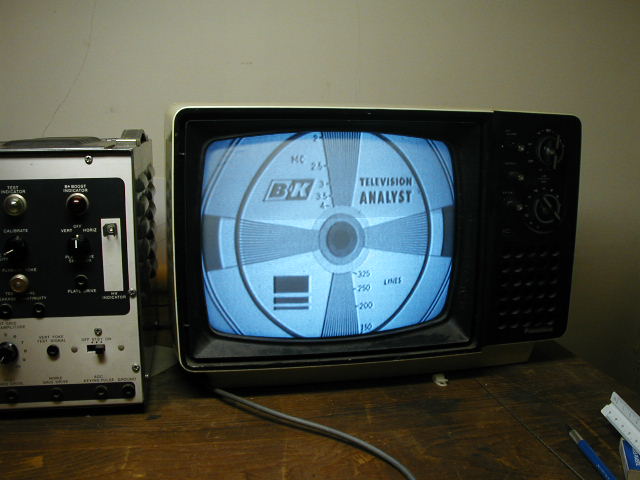
Below, a close-up of the pattern on the TV screen.
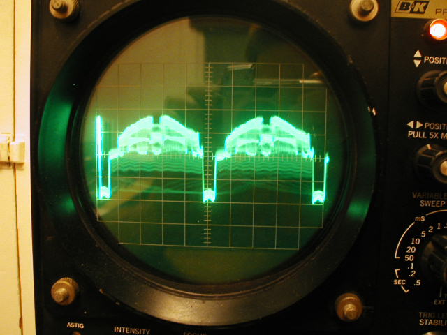
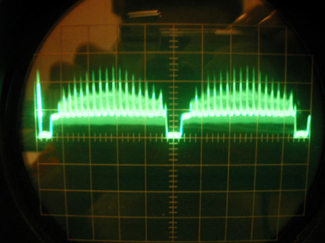
Below, the scope trace for the video signal being displayed above. The deep valleys are the horizontal sync pulses.
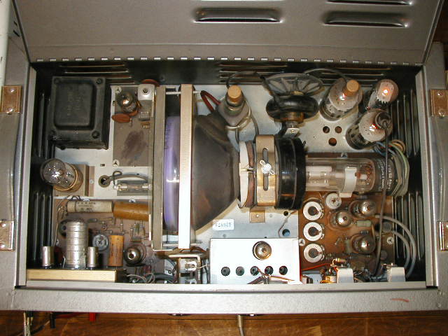
How does the TV analyst produce these images? Inside the 1076 is a flying spot scanner. To the left is a photo multiplier tube, to the right is a conventional CRT with a purple (violet) phosphor. The photo multiplier tube is most sensitive to this color.
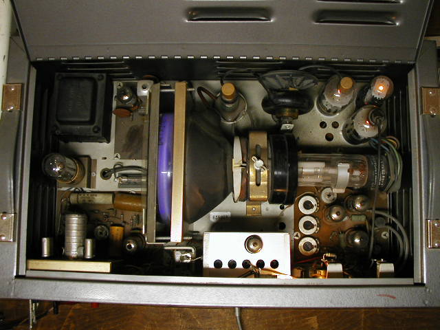
Below, an end view of the CRT
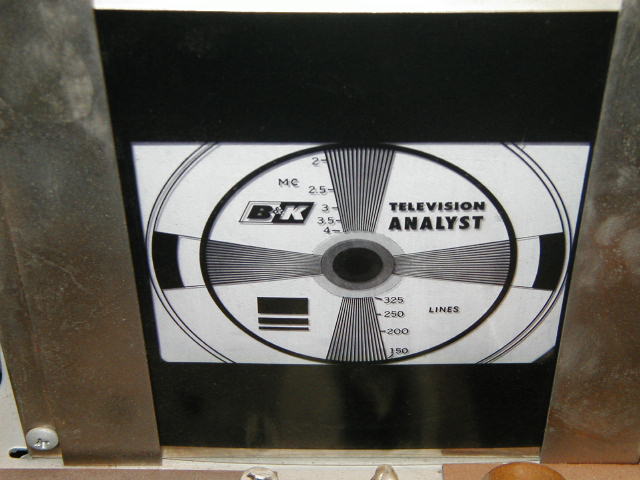
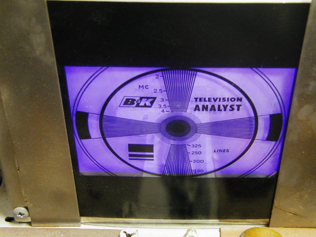
Below, a close-up of the pattern. The pattern is printed on a transparent slide. We will look at a few other slides with different patterns.
Another view of the pattern showing the purple color of the CRT display.
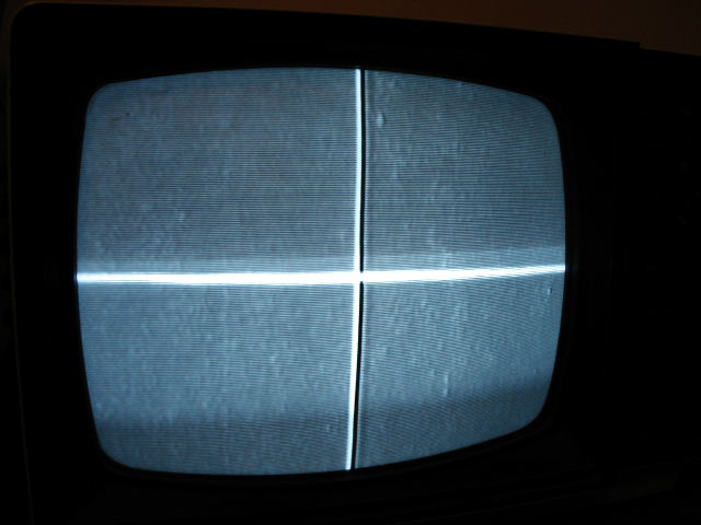
Below is a photograph of the image produced by another slide, two intersecting white lines.
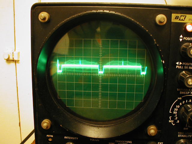
This is the video signal for the above image.
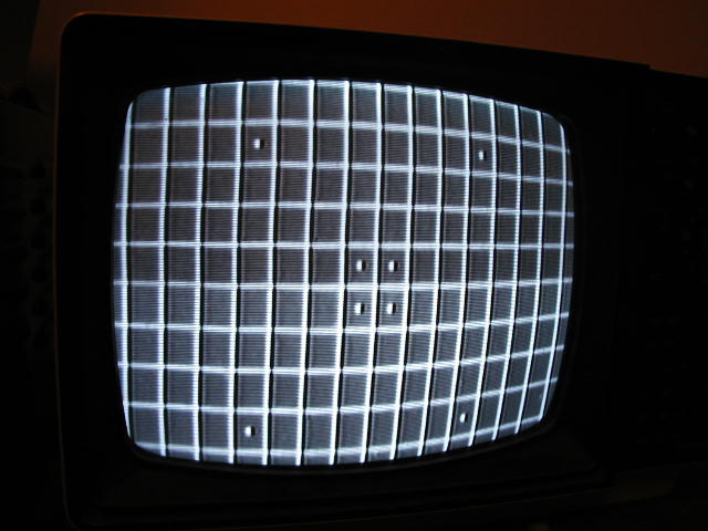
Here is a grid pattern slide, a white grid on a black background.
Here is the corresponding video signal trace.
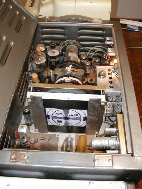
Below is another picture of the interior of the 1076, taken with a flash. Note the two Horizontal output tubes. One of these tubes drives the CRT deflection coils and flyback for the flying spot scanner, the other is used as a vertical or horizontal plate driver.
This allows the user to actually substitute the 1076's drive in place of the drive in a faulty receiver. Other signal and voltage sources include: calibrated -25 to +25 volt bias voltages; -50 to +50 ssync signals; composite video signal; 4.5MHz audio IF carrier; 400Hz audio tone; any IF frequency between 20 and 48MHz; RF outputs to channels 2-8, 12, and 13; AGC keying pulse; HV indicator probe; Boost B+ indicator; and a flyback/yoke tester that will detect shorted turns.
You may also want to see The Labguy's B&K 1077B TV Analyst.
Back to Radio/Electronics Page