
This 5 tube stereo amplifier is based on the output stage of your typical late 1940's 6-tube AM radio amplifier design. Its simplicity invites a little experimentation from those who enjoy tinkering.
I get a lot of inquiries about this design. Here is a little history of the design: I designed this amplifier as a stereo version of the output section of an old Trutone radio (made c.1947) I was using with my computer in 1999 (I connected the computer audio to the radio's phono input). The Trutone radio has an 8" electrodynamic speaker that I had re-coned in 1997 and sounded really nice. I used this homebuilt amplifier with some old 12" speakers from a Magnovox console. I made very minimal modifications to the design, and used the amp for about two years before parting it out for other projects.
After doing some recent work recapping my old Trutone, I thought I would freshen this page up a bit. As you can see, I have redrawn the schematic and simplified it greatly by removing the tone controls (something I should have done in the first version). I have also changed the tube line-up to more accurately reflect the prototype. I have also corrected a few typos. In older versions of this page, the output transformer impedance was given as 7600 ohms, it is actually 3300 ohms.
In Construction, the 5 volt secondary of the power transformer will go to the filament pins 8 & 2 of the 5Y3-GT tube. The 6.3 volt winding will go to the other tube filaments.
| CAPACITORS | |||
| ID | Function | Capacitance | Rating |
| C1, C4 | B+ decoupling | 200mmF Silvered Mica | 600v |
| C2, C5 | AF coupling grid 6V6 | .047mF Metallized polyester | 600v |
| C3, C6 | Output cathode bypass | 22mF Electrolytic | 25v |
| C7 | Filter | 47mF Electrolytic | 450WVDC |
| C8 | Filter | 33mF electrolytic | 450WVDC |
| C9 | Line bypass | .01mF Ceramic | 1400v |
| RESISTORS | |||
| ID | Function | Value (ohms) | Wattage |
| R1A & B | Volume Control | 500K Dual Pot | Audio taper |
| R2, R6 | Feedback | 1 meg | 1/2 |
| R3, R7 | Plate load | 470K | 1/2 |
| R4, R8 | Grid bias | 220k | 1/2 |
| R5, R9 | Output cathode bias | 330, wire-wound or metal oxide | 2 |
| R10 | Voltage divider | 750, wire-wound | 20 watts |
| Power Transformer, T1 | |||
| Primary | Sec. 1 | Sec. 2 | Sec. 3 |
| 117v 60 cycles | 600v CT @ 80ma | 5v @ 2A | 6.3v @ 4A |
| Audio Output Transformer T2, T3 | |||
| Primary (impedance) | Secondary (impedance) | ||
| 3300 Ω @ 400 cycles | 4 or 8 Ω @ 400 cycles | ||
| Tube | Function | ||
| 6SQ7-GT | AF Amplifier-Left | ||
| 6V6-GT | Output-Left | ||
| 6SQ7-GT | AF Amplifier-Right | ||
| 6V6-GT | Output-Right | ||
| 5Y3-GT | Full-wave vacuum rectifier |
Notes
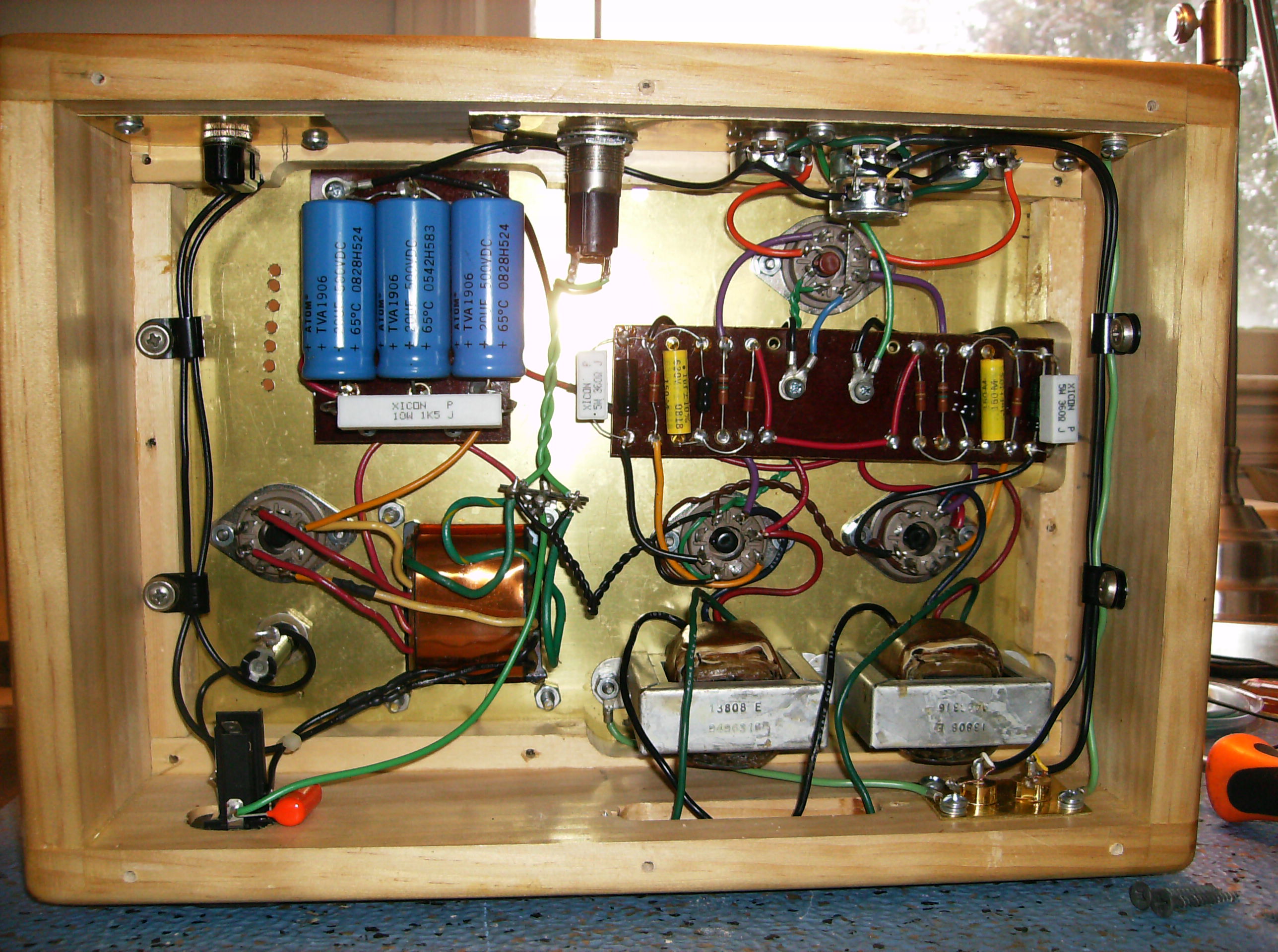
2-7-14 George in Ohio, who also built the amp featured on the 9-tube amp page, emailed me about this amp and included these three photos and had this to say:
"Wes, I built the 5 tube stereo too, about 3 years ago. Told my wife it is hers. She uses it on her computer. It has wonderful tone, and big sound. She loves it, and listens a lot to streamed music. I highly suggest this as an easier project for first timers. The card is for scaling purpose. Thanks again George"
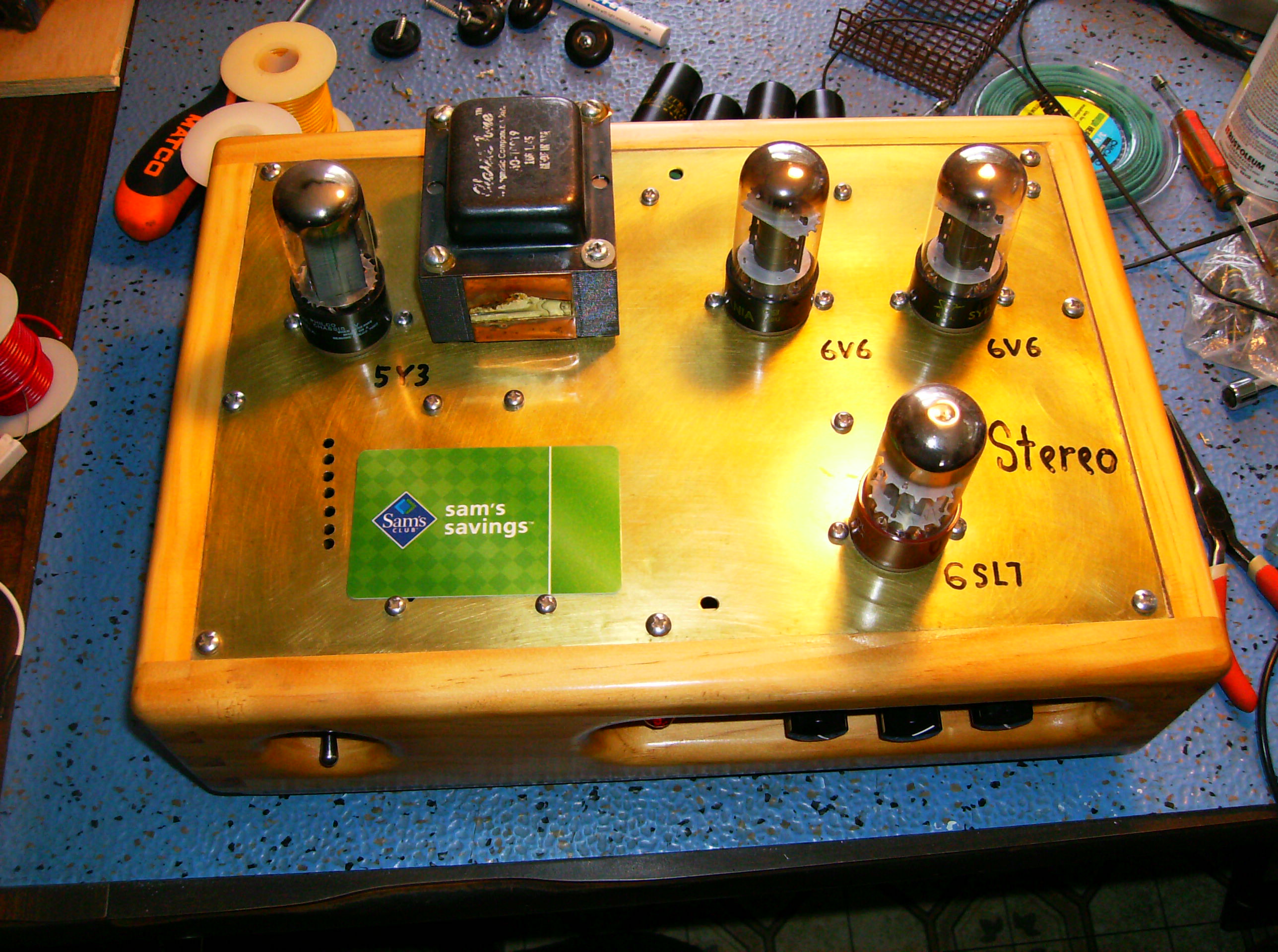

Thanks George for sharing the photos of the beautiful amp you've built! As you can see, big tube sound does not need to take up lots of space.
Updated 2-7-14
Back to The Radio & Electronics Page